How to Use PICAXE
PICAXE microcontrollers are a brand of PIC (Programmable Integrated Circuit). They come loaded with the PICAXE firmware which allows you to program them easily using a computer and a PICAXE USB cable. PICAXE offer a variety of different chip sizes with different amounts of pins for inputs and outputs. They also offer a variety of different software to program the PIC with; some of them use flowcharts while others use a written programming language called BASIC. For datasheets for PICAXE kits click here. For PICAXE software download click here. For a guide to getting started with PICAXE read on below.

What do I need to get started?

What you need can depend on your project but there are several basics that you will always require, they are:

how_to_use_picaxe_560_01

What are the different chip sizes for?

There are several different PICAXE chip types, the 08M2, 18M2 and 20M2. The number at the start describes the number of legs the chip has, this ranges from 8 legs to 20 legs (for ICs stocked by Kitronik), though versions are available with up to 40 legs. The more legs the PICAXE chip has the more inputs and outputs it has. The chart below shows the differences:
Chip Name
Number of Inputs and Outputs
Number of Analogue Digital Converters
08M2
5 (3 IN or OUT) (1 IN only) (1 OUT shared with programming pin)
0-3
18M2
16 (14 IN or OUT) (1 IN only) (1 OUT shared with programming pin)
0-10
20M2
16 (16 IN or OUT)
0-11
When it comes to selecting a chip size for a project it is important to make sure it has enough inputs and outputs to fulfil the specification of the project. In general it is better to select a larger chip and have some pins remain unused than to have too few pins to complete the project.

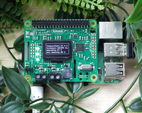
Selecting a circuit for your PICAXE Chip

The easiest way to get started is to buy a development board for the chip size you have selected. This contains the resistors and the connector required to program the chip. A diagram of this can be seen below.

how_to_use_picaxe_560_02

The most commonly used chip is the 08M2, which can be used with the Kitronik Development Board. This board gives you an IC socket to put the chip into, terminal blocks for quickly attaching inputs and outputs and an on board stereo jack where the programming cable can be inserted. For the larger PIC chips there are 18 pin development boards and 20 pin development boards.

Drivers for the PICAXE AXE027 Programming Cable

Before the AXE027 USB cable can be used on Windows or Mac computers you must install the 'USB driver' software. Linux/Chromebook have a preinstalled driver by default. The USB driver tells the Windows/Mac operating system how to use the USB cable. It is a separate, one-off installation that needs to be carried out the very first time you want to use the cable. Once installed the computer automatically 'remembers' the settings for next time you want to use the cable. The installation is very straight forward:
  • Make sure the AXE027 USB cable is not plugged in to the computer.
  • Download the drivers for your operating system from this driver download link.
  • Run the downloaded driver installation program.
  • Insert the AXE027 USB cable and follow the on-screen prompts.
When using the programming cable, always insert the USB cable into the PC a few seconds before starting the PICAXE software. Always use the AXE027 USB cable in the same USB socket on your computer, this ensures that the virtual COM port setting will always remain the same. Many PICAXE users mark the correct USB socket and cable with a coloured dot to remind them which socket to use.

Software for PICAXE

Free software is available for download from https://picaxe.com/software// for programming the PICAXE microcontrollers. The recommended software for Windows at the time of writing is PICAXE Editor V6. Before running the program make sure that the PICAXE cable is plugged in. When the software is ran it will open a window like the one pictured below. From the drop down menus the user needs to select the PICAXE type and the COM port. Clicking the New Flowchart button opens a blank grid allowing the creation of a new program. A simple example of flashing an LED is described below.

how_to_use_picaxe_560_03

Next select the Output command from the common command list and drag and drop it below the start bubble on the flowchart.

how_to_use_picaxe_560_04

Double clicking the Output command that was just placed will open a window that allows the user to toggle all the inputs on or off. In the picture below C.0 has been toggled on and no command has been issued any of the other pins.

how_to_use_picaxe_560_05

A useful tool is the diagram of the chip in the bottom left corner of the screen. This has its legs labelled in a way that matches the output window you just opened. The labels correspond to the pins that can be toggled on or off. The outputs C.0, C.1, C.2 and C.4 correspond to pins 7, 6, 5 and 3 respectively on the IC.

how_to_use_picaxe_560_06

Then select the wait command and place it below the output command. Double click the bubble and it will bring up another window. Pick 1 second from the drop down to set the wait time.

how_to_use_picaxe_560_07

Next, another output command is needed to turn the output back off. This is done the same way that it was turned on, by clicking on the box next to the output until it turns red.

how_to_use_picaxe_560_08

The last command needed is a second wait command for 1 second. This can be added by selecting the first wait command that was placed and pressing Ctrl + C then by clicking on the empty box below the second output command and pressing Ctrl +V.

how_to_use_picaxe_560_09

The last step is to click the line tool then drag a line from the bottom of the flowchart back to the first bubble you placed. This will make the program loop. Before continuing, make sure that the circuit is powered up, the IC is in the circuit the correct way around and that the programming cable is all the way into the stereo jack on the PCB. Once this has been done, click the ‘Program’ icon on the top bar visible on the image below. The program will download to the IC and run immediately. The program should toggle output C.0 on for one second then off for one second and repeat forever. The programming cable can be removed once the program has downloaded and the program will continue to run whenever the chip is turned on.

how_to_use_picaxe_560_10

Troubleshooting

If the program is not downloading to the PICAXE microcontroller there are a few common mistakes to check for.
  • Check the PCB, is the chip in the board the correct way around?
  • Is the programming jack all the way in the audio socket?
  • Is the board connected to a suitable power supply and switched on?
  • On the software, has the correct model of PICAXE chip been selected the from the drop-down menu?
  • Has the correct COM port been selected?
  • Is the program valid? If the flow chart has ‘dead ends’ it may not compile.
  • If the software is being used for the first time, there may be an issue with the driver for the USB cable.
  Download a pdf version of this page here. pdf_icon.gif

Leave a comment

All comments are moderated before being published