0
Your Cart
0
Your Cart

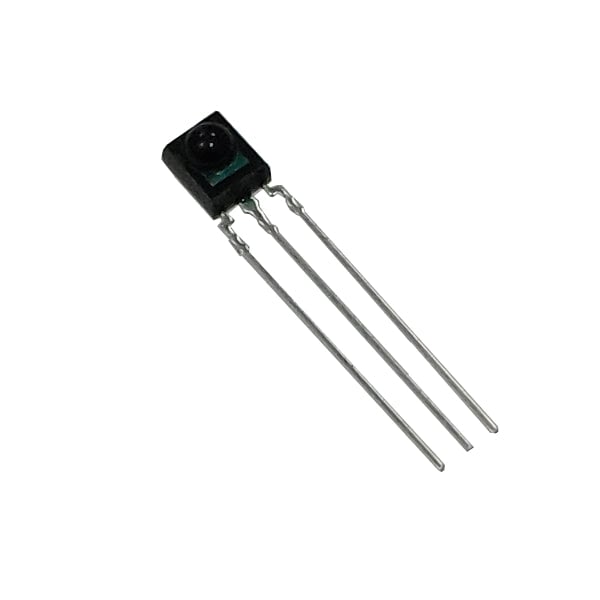
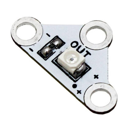
Miniature size, built in exclusive IC infrared receiver module. Designed to be used with the Infrared 5mm Water Clear LED.. Provides a wide half angle and long reception distance with good noise-proof capability.

Infrared receivers have a high immunity against ambient light due to infrared having a shorter wavelength than visible light. This module is mounted as a side view.

These receiver modules are found in AV systems, home appliances and can be used as a remote control for wireless devices.


Features:

  • Receives Infrared light signals.
  • Wide half angle.
  • Long reception distance.


Contents:

  • 1 x Infrared Receiver Module.


Dimensions:

  • Total Height: 33mm.
  • Receiver Head Height: 7mm.
  • Height of legs: 26mm.
  • Width: 5mm.


Requires:


Resources:

Documents & downloads

Related resources

This product doesn't have any resources.

Reviews

There are no reviews yet.

Be the first to review “Infrared Receiver Module”

Your email address will not be published. Required fields are marked *

Questions and answers

    is the infrared receiver module 35111 the same as the TSOP1738 or is it an equivalent. The TSOP1738 has its frequency set. at 38khz. Is the one illustrated the same?
  1. 0 votes
    Q is the infrared receiver module 35111 the same as the TSOP1738 or is it an equivalent. The TSOP17...... Read more
    Asked by Anonymous on November 14, 2016 12:00 am
    Answered by the admin Hi,


    The typical center frequency is 37.9kHz.
  2. Hi, I have this and the recommended LED but are unable to get them to work together. Please can you suggest a suitable circuit setup/connection for both parts. Also on the data sheet the pin numbers seem different on the 2 diagrams, can you confirm which is correct.
  3. 0 votes
    Q Hi, I have this and the recommended LED but are unable to get them to work together. Please can y...... Read more
    Asked by Anonymous on March 17, 2016 12:00 am
    Answered by the admin Hi,


    Both pin diagrams are correct. The one at the top is the one you should look at to see which pin is which. The circuit diagram at the bottom moves them around to keep to the convention of having the positive rail at the top and the negative rail at the bottom, it is not a mechanical drawing as such.
    Getting these two items to work together requires a bit of know-how.
    The IR receiver filters out IR light that isn't flashing at near 37.9 kHz.  You need to flash your LED at a frequency as close to that as possible for it to be recognised. This allows it to distinguish your signal from background IR radiation. 
    The sensor looks for "bursts" of IR at this frequency, when it detects a burst of IR at this frequency the output pin drops from being near the supply voltage to nearly 0V.
    The best way to get this working is with a microcontroller like a PICAXE or Arduino. Some have built  in protocols or libraries for IR communication. You can get something more primative working with a 555 timer in an astable configuration to acheive the 37.9 kHz then a push to make switch to let the signal through to the LED. 
To submit a question, please login or create an account