This is a step-by-step guide for using free design tools to create 2D and 3D designs for 3D printing. The project introduces basic 3D design concepts by modelling a resistor lead-forming tool that ensures all resistors in a project are bent identically, ideal for neat, consistent PCB assembly. The designs and printing were completed by someone new to both 3D design and 3D printing, demonstrating how accessible these tools can be. If you want to print the tool immediately, an STL download is available at the end of this article.
Note: Autodesk has discontinued all 123D Apps. Their features now live in Tinkercad, Fusion 360, and ReCap Pro. More information is available here.
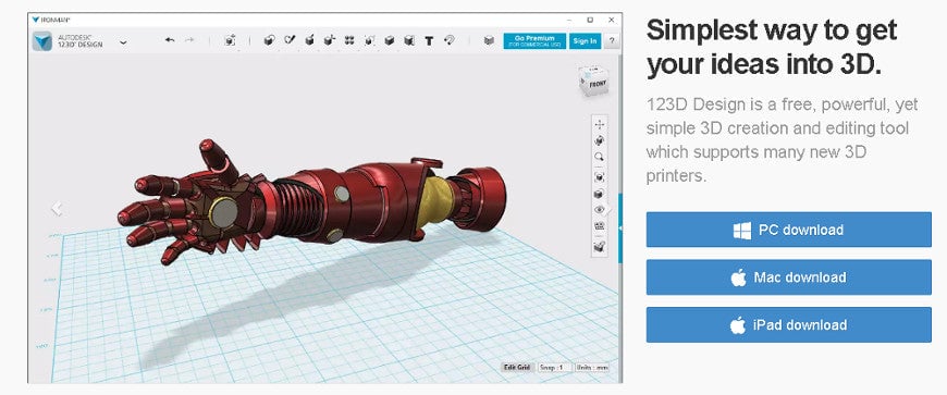
We chose Autodesk 123D Design because it was free for schools, had a shallow learning curve, and was more than capable of producing the tool.
Level of Difficulty
- Beginner
You Will Learn
- How to approach the design process
- How to create a 2D design
- How to turn a 2D design into a 3D model
- How to export the design for 3D printing
You Will Need
- Autodesk 123D Design
- A 3D printer such as a Robox
The Process
- The design aims
- Taking physical measurements
- Creating a 2D design
- Extruding the 3D model
- Exporting and printing
Step 1 – Establishing the Design Aims

We wanted a tool that would bend resistor leads uniformly so that each resistor sits neatly on a PCB with the body centred between the holes. The tool needed to be simple to design, easy to print, and long enough to handle comfortably. Additional design considerations emerged once we measured a resistor.
Step 2 – Taking Physical Measurements
Using Vernier callipers, we measured all aspects of a resistor. Most of our kits use 1.0 cm hole spacing, but we designed the tool to support multiple spacings: 0.7 cm, 0.8 cm, 0.9 cm, 1.0 cm, 1.1 cm, and 1.2 cm.
We also researched commercial tools to confirm our initial ideas aligned with typical layouts.
Step 3 – Creating a 2D Design
After experimenting in 123D Design, we found the entire tool could be sketched in 2D and then extruded. All sketching was done using tools from the Sketch menu.

The images below show the order in which each part of the 2D design was drawn.

The centre section, where the resistor body rests, was drawn as a rectangle with filleted ends.

Next, we added the lead-channel sections. Although resistor leads are typically 0.5–0.6 mm thick, we made the channels 1 mm wide to avoid stressing the printer.

We then added the remaining physical features, including a hanging hole and side channels to assist with bending.

Finally, we removed unnecessary construction lines, leaving only the centre line to help position text later.
Step 4 – Extruding the 3D Design & Adding Text
Extruding

The centre section was extruded by 3 mm.

The lead-channel sections were extruded by 4 mm.

The remaining areas were extruded to 5 mm.
Adding Text

Text can be difficult to print cleanly, so we used 5 mm bold text. The tool name and ohm symbol were extruded by 1 mm, and the spacing labels by 0.2 mm.
Step 5 – Exporting & Printing

When exporting, ensure you select Combine Objects so the printer treats the model as a single piece. Our Robox printer uses Automaker, which automatically configures temperatures and print settings.

After importing the STL, we positioned the model flat on the bed for best results.

Download
If your students create this or a similar project, feel free to send photos to our gallery at gallery@kitronik.co.uk.