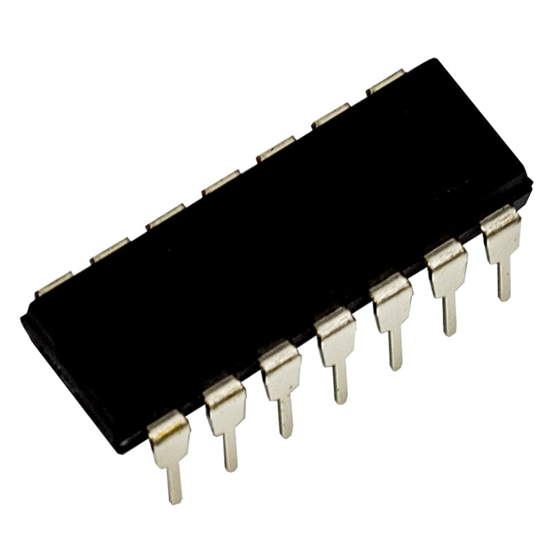
A BCD to 7 Segment Decoder Driver made up of CMOS logic and NPN transistors. It can drive LEDs and other displays directly. It has sufficient output current to directly drive a seven segment display.Supplied in a 16 pin DIL package.
Pin Out information:


The following table explains what the pins do:
| Pin Name | Input/Output. | Description. |
|---|---|---|
| A – D | Input | A to D are the binary input lines |
| a – g | Output | a to g are the output lines, to drive the seven segment display. See segment diagram above |
| LT | Input | Lamp Test (active low) Low = turns all segments on for testing purposes High = normal operation |
| BI | Input | Blanking (active low) Low = turns all segments off High = Displays the required number The blanking pin can be used with a high speed variable width square wave to provide a dimming function |
| LE | Input | Latch Enable (active high) Low = normal operation High = previously displayed number is latched and held |
Truth table
| Inputs | Outputs | ||||||||||
| D | C | B | A | a | b | c | d | e | f | g | Display |
| 0 | 0 | 0 | 0 | 1 | 1 | 1 | 1 | 1 | 1 | 0 | 0 |
| 0 | 0 | 0 | 1 | 0 | 1 | 1 | 0 | 0 | 0 | 0 | 1 |
| 0 | 0 | 1 | 0 | 1 | 1 | 0 | 1 | 1 | 0 | 1 | 2 |
| 0 | 0 | 1 | 1 | 1 | 1 | 1 | 1 | 0 | 0 | 1 | 3 |
| 0 | 1 | 0 | 0 | 0 | 1 | 1 | 0 | 0 | 1 | 1 | 4 |
| 0 | 1 | 0 | 1 | 1 | 0 | 1 | 1 | 0 | 1 | 1 | 5 |
| 0 | 1 | 1 | 0 | 0 | 0 | 1 | 1 | 1 | 1 | 1 | 6 |
| 1 | 0 | 1 | 1 | 1 | 1 | 1 | 0 | 0 | 0 | 0 | 7 |
| 1 | 0 | 0 | 0 | 1 | 1 | 1 | 1 | 1 | 1 | 1 | 8 |
| 1 | 0 | 0 | 1 | 1 | 1 | 1 | 0 | 0 | 1 | 1 | 9 |


Reviews
There are no reviews yet.