We love a throwback here at Kitronik, and what better is there than a classic prop from a beloved 80s movie? We must have bumped our heads while hanging a clock by standing on the toilet to have come up with this one!
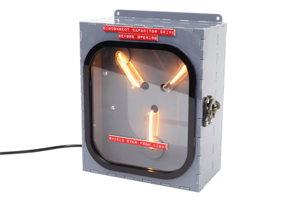
The Flux Capacitor, a fictional component of the time-travelling DeLorean from Back to the Future, is an instantly recognisable prop with a distinctive look and strong potential for laser cutting, 3D printing, electronics, and hard craft skills. While we haven’t been movie-accurate, we wanted to have a go anyway, and we can’t wait to show you how! Just bring your own DeLorean…
A note before we begin: we used the hinges and clasp from one of our wine boxes for the enclosure, so we recommend measuring the hardware you select and adjusting the screw holes to fit.
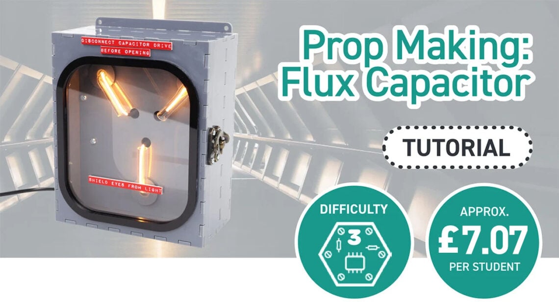
*Price per student calculated based on exVAT prices and on using the designs provided with the exact materials and kits we used. Background Image by MontyLov on Unsplash.
This Make Covers:

What did we use?
- Red on White Laser Laminate (43213)
- Grey Value Acrylic (43321)
- Clear Value Acrylic (43185)
- Black Value Acrylic (43186)
- 8mm Acrylic Tube (4907)
- Flexible LED Noodle USB Lamp Kit (2186)
- 4 x M3 6mm Pan-Head Screws (2309)
- 2 x M3 8mm Spacers (2306)
- 12 x M2 6mm Pan-Head Screws (2316)
- 12 x M2 Hex Nuts (2325)
- Hinges and a Clasp
- Soldering Equipment
- Superglue
- A Laser Cutter
- The design DXF.
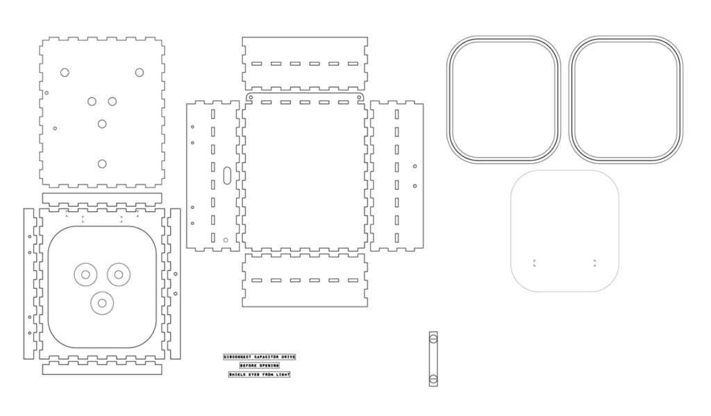
Step 1 – Check out the design files.
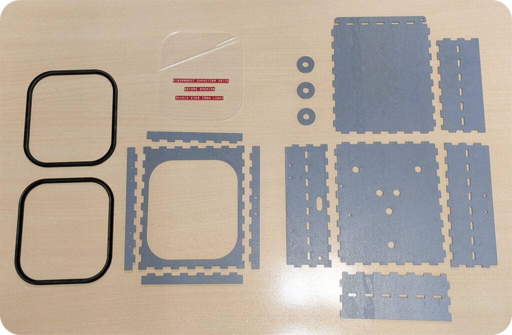
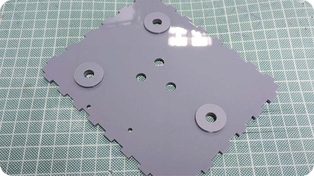
This DXF contains the designs for this project, and will appear as shown below when you open it. Make sure to amend the hinge and clasp holes for the hardware you choose – ours fits the hinges and clasp from one of our wine boxes.
Step 2 – Laser-cut the Flux Capacitor.
We’ve cut the enclosure from 3mm thick Grey Value Acrylic, Black Value Acrylic, Clear Value Acrylic, and then the engraved labels were made using Red on White Laser Laminate.
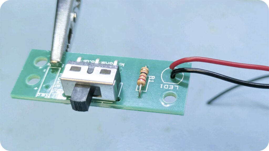
Step 3 – Begin assembling the electronics.
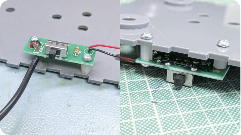
Using the Flexible LED Noodle USB Lamp Kit, we will only be using one of the five noodles and the corresponding PCB and components. Begin by soldering the switch and resistor onto the PCB, and then add the LED wires. We used about 20cm of each, though you may not need that much depending on how you choose to route the wires. Use the red wire for positive, and black for negative – the negative side is the flat side of the LED outline on the board.
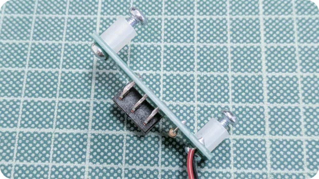
Step 4 – Add Spacers to the bottom of the PCB.
These will hold the PCB beneath the internal panel.
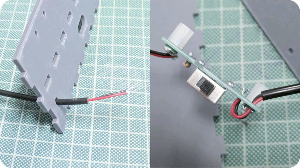
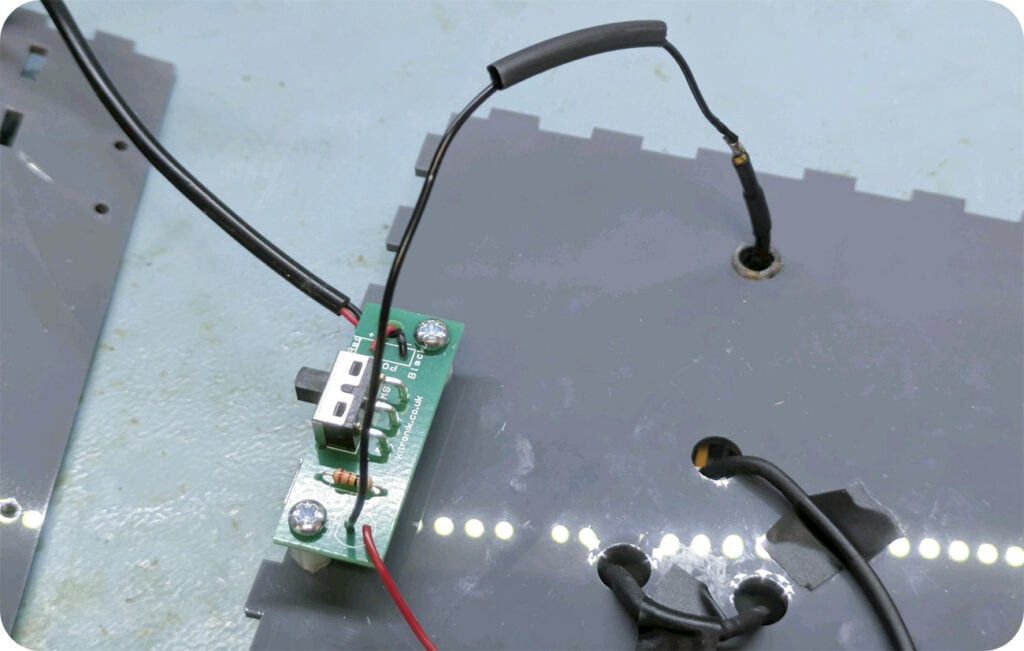
Step 5 – Attach the USB power cable.
First, feed it through the hole in the bottom of the panel with the hinge screw holes and switch hole, then solder to the PCB, making sure to pass the wires through the strain relief hole before doing so.
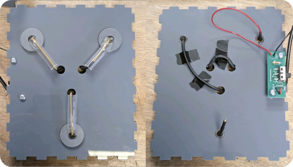
Step 6 – Assemble the internal panel.
These rings are purely decorative, so this step could be skipped if you choose to customise the design differently. We used superglue sparingly to affix them in place precisely so that the holes at the centre match the holes on the internal panel.
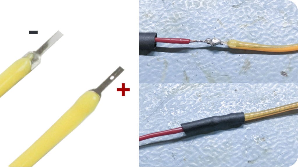
Step 7 – Attach the noodle to the positive LED wire.
Solder the wire in place to the positive side of the noodle, which as shown in the image below is the side with the single small hole in the metal tab. Use a small amount of heat shrink to insulate the new joint.
Step 8 – Attach the PCB to the internal panel.
Using the last two 6mm M3 pan-head screws, affix the PCB to the bottom of the internal Panel, with the switch facing the outside edge of the panel.
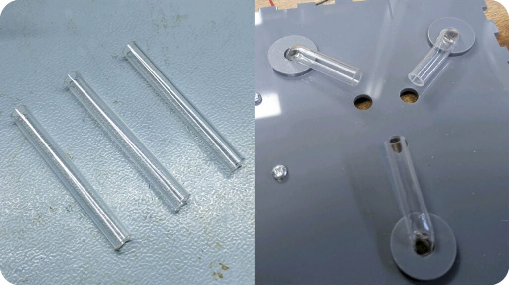
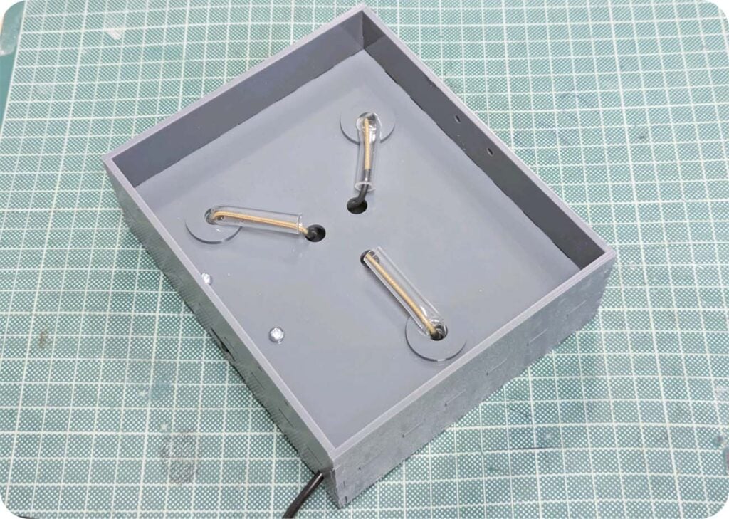
Step 9 – Cut and bend the acrylic tubes.
Cut 3 lengths of the acrylic tube approximately 5cm each, then one at a time heat one end of the tubes gently with a heat gun, line bender or other acrylic heating device, and feed them up through the holes in the internal panel and bend it so that they lay horizontally against the internal panel as shown.
Step 10 – Feed the noodle through the tubes.
Weave the noodle through the tubes, optionally using heat shrink to hide the areas of the LED noodle not inside the tubes as you go.
p 11 – Solder the negative side of the noodle.
To complete the circuit, slide a length of heat shrink on to the black LED wire, then solder the other side of the noodle (the tab on this side has no hole in it) onto this wire. Then slide the heat shrink over the solder joint and shrink it in place gently.
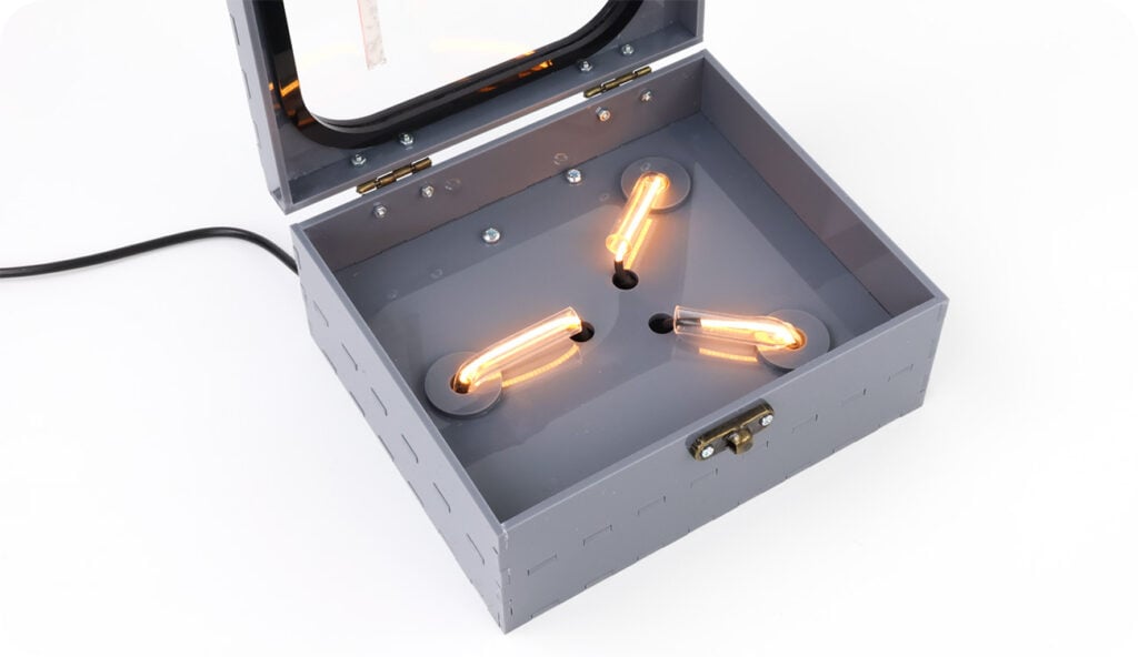
Step 12 – Construct the box.
Around the internal panel and base panel, build the four sides up and use superglue to secure in place. The decorative mounting holes on the base panel should face the top of the box, so that once displayed the box can sit upright with no obstructions.
Make sure that the panel with the hinge holes are on the left side, and the clasp holes are on the right.
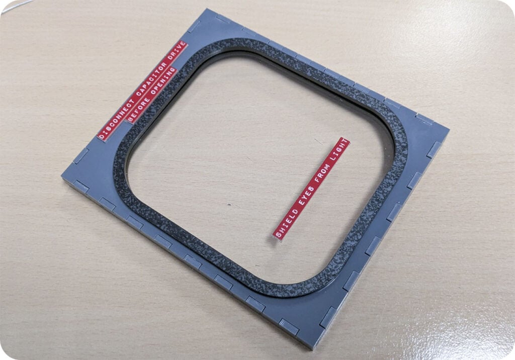
Step 13 – Construct the lid
As shown, build the lid, using the black “rubber seal” pieces to suspend the window in place, and using superglue sparingly to secure all pieces in place except the labels. These should be attached with double-sided tape to avoid misting on the window.
Make sure that the panel with the hinge holes are on the left side, and the clasp holes are on the right.
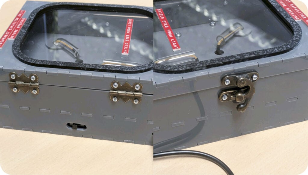
Step 14 – Attach the lid to the box with hinges and a clasp.
As mentioned, the hinges and clasp we used were from one of our wine boxes. Make sure that whatever hardware you choose, the holes in the box for these are amended to fit.
This is where we used the M2 screws and hex nuts, but your hardware may require different sized screws.
Step 15 – You’re Finished!