
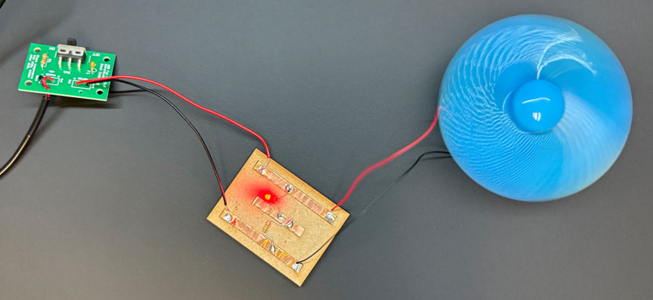
This tutorial shows how copper track tape can be used to create a small circuit board, in this case to expand the Kitronik fan kit to include a power LED using only a few extra materials
This make Covers:
- Design
- Soldering
We Have Used:
- Kitronik USB Fan Kit (2162)
- Copper Tape – With Non Conductive Adhesive 5mm x 15m (2478)
- Red 5mm Diffused LED – 275mCd (3504)
- Resistor, pack of 100 – 150R Resistor (3003-150R)
Prepare the board
Here is an image of our completed fan kit without LED, which we will be using as the base project:
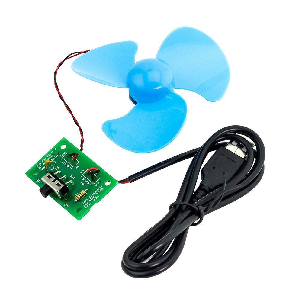
Before starting this tutorial, make sure there is no power to the board.
To add the LED, we need to make a secondary circuit board, as our current one has no more space for additional components.
We used a small piece of MDF to do this, but any rigid heat resistant material will do the job, if you use porous materials like plywood, then you may need to seal the material with a coat of watered down PVA in order to make sure the copper track tape bonds well.
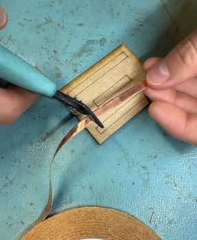
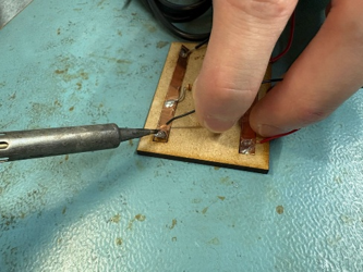
We then cut to size three strips of adhesive-backed copper tape and applied them to the MDF. When sticking the tape on the board it is important that it is firmly pressed down, otherwise it will start to curl at the ends. The copper tape needs burnishing, to ensure a it is flat to the MDF and without air bubbles. The rounded end of the handle on a file, screwdriver or any other tool is suitable for the job. The markings on the image show you how to keep them spaced apart. The copper tape will act as the tracks in the circuit board to apply solder to.
Solder the LED & resistor
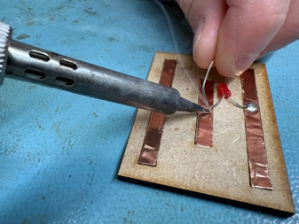
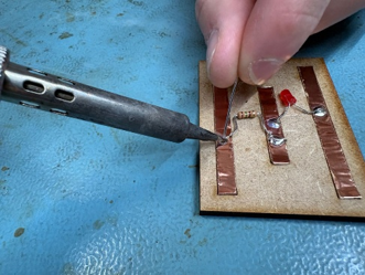
Then, we soldered the LED to the middle and top strip of copper. The flat edged side of the LED (which is also the shorter leg) should be soldered to the middle copper strip. Depending on your enclosure you may wish to solder flying leads to the LED before connecting it to the board.
Next, we soldered the resistor to the middle copper strip and the empty copper strip.
Connect to the fan PCB
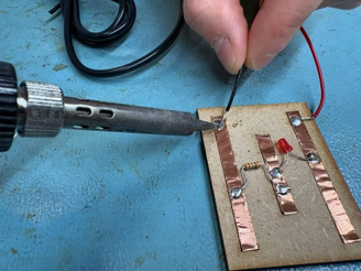
Cut some spare black and red wire to solder in the holes marked ‘motor’ on the PCB and strip the ends. Ensure you solder the red wire to the hole marked ‘red’ and the black wire to the hole marked ‘black’. Then, solder the other end of the red wire to long copper strip that the LED is soldered to.
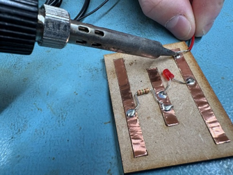
Solder the other end of the black wire to the long copper strip that the resistor is soldered to.
Connect the fan
Next, solder the red wire from the fan to the copper strip that the red ‘motor’ wire is soldered to.
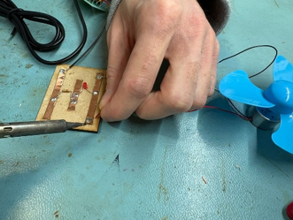
Finally, solder the black wire from the fan to the copper strip that the black ‘motor’ wire is soldered to.
Turn on your PCB and you should see the LED light up and the fan spin at the same time!