Note: Although this kit is no longer available, we do still carry a number of robotic buggy kits here.
About the Buggy:
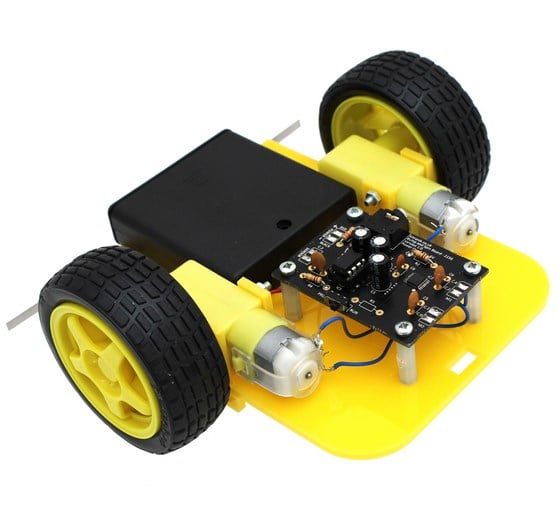
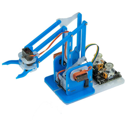
The Bump and Spin Buggy is an easy to assemble introductory kit which makes use of our Bump and Spin Kit to look at entry level robotics and allow you to quickly and easily make a working wall-sensing buggy. By following the step-by-step instructions (below) and downloading the sample program, you can program the buggy to your own specific requirements and get the buggy running in no time!
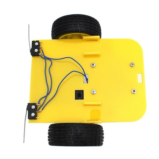
The buggy is a robot that is aware of its surroundings. Using two strategically placed microswitches the buggy is able to detect when it hits a solid surface, allowing it to ‘bump and spin’ to avoid obstacles.
Note:
A PICAXE USB Download Cable is required in order to program the buggy.
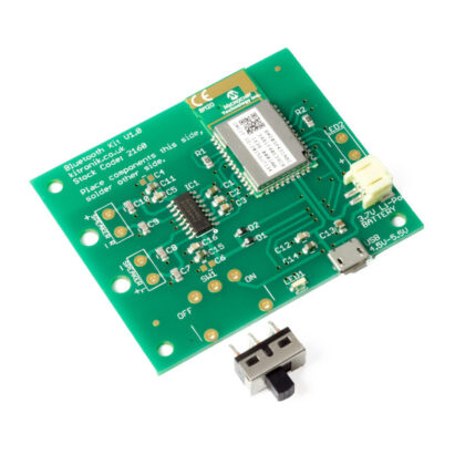
About the PCB:
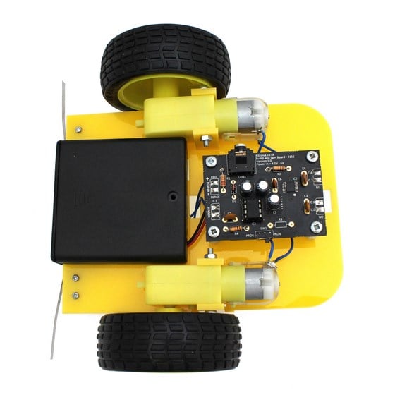
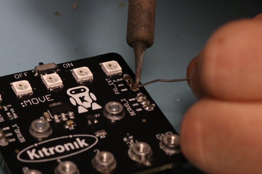
The chassis of the buggy has been designed to take the hassle out of designing a buggy, is quick and easy to assemble and includes an easily accessible on/off switch. The buggy is based on the programmable PICAXE 08M2 chip and includes the DRV8833 Motor Driver IC which is able to drive two 6V motors bi-directionally. The motor driver IC is pre-mounted on the PCB, leaving the remaining capacitors, resistors and other components to be soldered to complete the kit. The bump and spin buggy takes care of the mechanics so you can focus on the electronics and programming it!
Programming the Buggy:
The kit is supplied with a 3.5mm stereo jack for programming. When programming the board a small slide switch needs to be set to ‘PROG’ and on completion be set to ‘RUN’ (This is done to make full use of the microcontroller IO pins). The input pads have a pull down resistor and a de-bounce capacitor allowing a switch to be connected to the board and the PIC programmed to respond to it with the minimum effort. The motors are driven by the DRV8833 motor driver IC which is pre-mounted on the board, this will drive 1.5A motors so has plenty enough power for most projects. The kit is supplied with a 4xAA battery cage to power the board.
Features:
- Buggy ‘spins’ and turns around when hitting an object.
- ‘Bump’ detection input on live bumper.
- Drives Two motors, with full direction control.
- Easily accessible on/off switch.
- 1.5 Amp drive per motor.
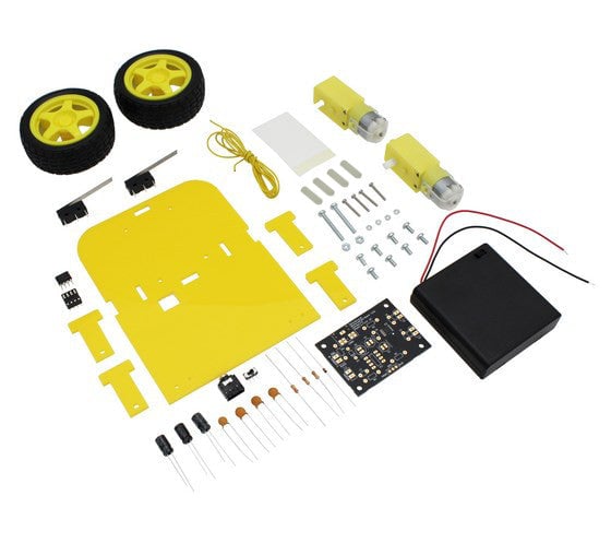
Contents:
Buggy Chassis Contents:
- 2 x Right Angle Geared Hobby Motor.
- 2 x Wheel for Geared Hobby Motor.
- 2 x Micro Switch (Long Lever).
- 1 x 4xAA Covered Battery Holder with Switch and Leads.
- 1 x Laser cut Perspex chassis.
- 2 x 30mm Pan Head M3 Machine Screws.
- 2 x M3 Nuts.
- 4 x 16mm Pan Head M2 Machine Screws.
- 4 x M2 Hex Nuts.
- 8 x 6mm Pan Head M3 Machine Screws.
- 1 x Approx. 3cm strip of 50mm Wide Double-sided tape.
- 1 x Approx. 1m length of Multi-Strand Cable.
- 4 x 20mm Plastic Spacers.
Bump and Spin PCB Contents:
- 1 x PICAXE 08M2.
- 1 x Stereo PCB Socket.
- 1 x Miniature PCB Mount Slide Switch.
- 1 x 1N4148 Signal Diode.
- 2 x 10K Resistor.
- 1 x 22K Resistor.
- 3 x Capacitor, Electrolytic, 16V, 220uF.
- 3 x Capacitor, Ceramic, 50V, 100nF.
- 1 x Capacitor, Ceramic, 50V, 10nF.
- 1 x IC Socket 8 Pin.
- 1 x PP3 Battery Clip Lead (Heavy Duty).
- 1 x Bump and spin PCB, pre-populated with the surface mount DRV8833PWPR motor driver IC.
Dimensions:
- Buggy Length: 160mm.
- Buggy Width: 165mm.
- PCB Length: 58mm.
- PCB Width: 43mm.
Video:
Requires:
- 4 x AA Batteries.
- Soldering Iron.
- Solder.
- Wire Cutters.
- A computer with PICAXE programming editor software or similar installed on it.
- PICAXE USB Download Cable.

Reviews
There are no reviews yet.