
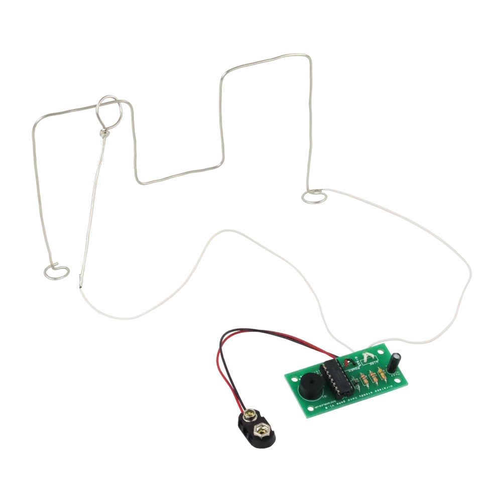
The Wireless Steady Hand Game Kit is an ideal introduction to basic electronic sensing and timing circuits. The player’s body completes the circuit between the handheld loop and the PCB, allowing the kit to demonstrate how resistance can be used as an input to electronic systems. When the loop touches the track, the change in resistance is detected and the buzzer sounds for approximately one second.
The circuit is built around a hex buffer IC. One stage is used to sense the resistance change at the input, while another stage, combined with an RC network, provides a simple timing function that keeps the buzzer active for a fixed duration. This makes the kit a useful example of how logic devices can be repurposed for analogue style behavior in educational projects.
The kit is supplied in a grip-seal bag and includes all components required for the build, making it suitable for classroom activities, clubs, or introductory electronics lessons. The kit is available as a single pack or as a 24 pack.
Note:
- This steady hand game kit kit requires soldering.
- This kit requires PP3 battery which is available separately.
Contents:
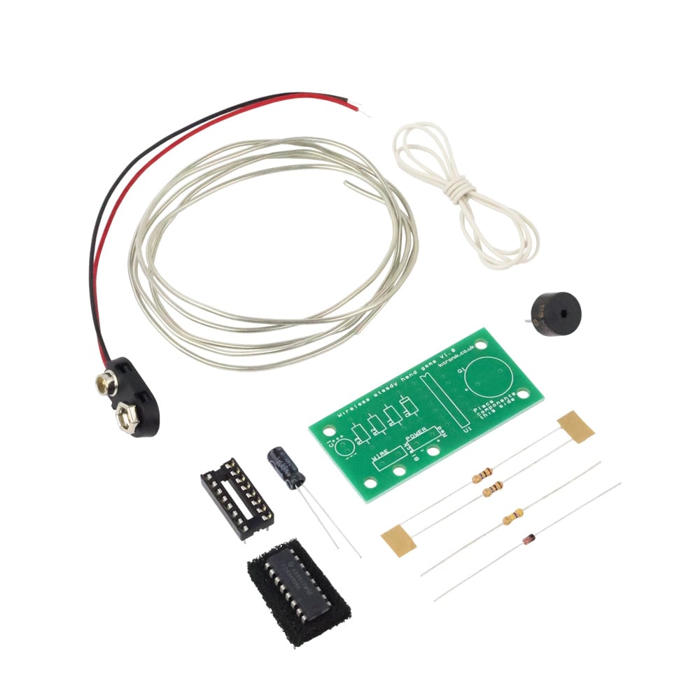
Each single pack contains;
- 1 x 10M resistor
- 1 x 470K resistor
- 1 x 1uF capacitor
- 1 x 1N4148 diode
- 1 x 16 pin IC holder
- 1 x Hex inverter buffer
- 1 x PCB mount Piezo sound (with drive)
- 1 x PP3 Clip lead
- 0.5m connecting wire
- 1m of tinned copper wire from a reel
Kit Variations;
This kit is available as a;
- Single Pack – 2140-10
- 24 Pack – 2140-24
Dimensions:
- Length: 57mm.
- Width: 27mm

Reviews
There are no reviews yet.