Introduction:
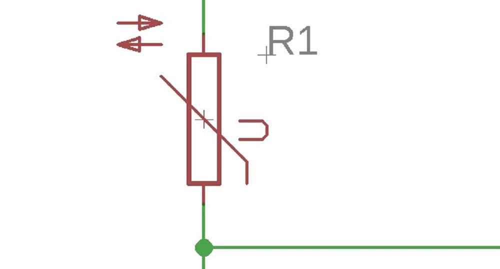
A thermistor is a component that has a resistance that changes with temperature. There are two types of thermistor, those with a resistance that increase with temperature (Positive Temperature Coefficient – PTC) and those with a resistance that falls with temperature (Negative Temperature Coefficient – NTC).Temperature coefficient:
The most common type of thermistors are those in which resistance decreases as the temperature increases (NTC). The amount by which the resistance decreases as the temperature increases is not constant, it varies in a non linear way. A formula can be used to calculate the resistance of the thermistor at any given temperature. Normally these are calculated for you and the information can be found in the devices datasheet.Thermistor Applications:
There are many applications for a thermistor, three of the most popular are listed below.Temperature sensing:
The most obvious application for a thermistor is to measure temperature, they are used to do this in a wide range of products such as thermostats.In rush current limiting:
In this application the thermistor is used to initially oppose the flow of current (by having a high resistance) into a circuit. Then as the thermistor warms up (due to the flow of electricity through the device) its resistance drops letting current flow more easily.Circuit protection:
In this application the thermistor is used to protect a circuit by limiting the amount of current that can flow into it. If too much current starts to flow into a circuit through the thermistor this causes the thermistor to warm up. This in turn increases the resistance of the thermistor reducing the current that can flow into the circuit.Example:
The circuit shown below shows a simple way of constructing a circuit that turns on when it goes hot. The decrease in resistance of the thermistor in relation to the other resistor which is fixed as the temperature rises will cause the transistor to turn on. The value of the fixed resistor will depend on the thermistor used, the transistor used and the supply voltage. Download a pdf version of this page here Learn more about the author read more »©Kitronik Ltd – You may print this page & link to it, but must not copy the page or part thereof without Kitronik's prior written consent.
24 comments
Mark Donnison
Hi Rhys, the properties of the materials used are to ensure that it operates in this manner which suits most applications.
Rhys
What causes a thermistor to non-linear? i know as the temperature increases the res drops but why?
Mark Donnison
Hi Sujan, The best way to measure it yourself would be to take measurements with an exact controllable heat source in a controlled environment and plot a graph. In most cases, the datasheet can provide more accurate information than you could obtain yourself.
Sujan
How to find exact temperature and resistance relation of a thermistor mainly NTC ?
Mark Donnison
Hi Augustus, its conductive properties change due to changes in temperature. Going deeper than that is beyond the scope of this tutorial. Wikipedia has more information on the properties of a Thermistor: https://en.wikipedia.org/wiki/Thermistor
Augustus
How does it work? Why does the resistance decrease? What happens inside of the NTC when temperature changes?
Mark Donnison
HI Jeng, thanks for getting in touch. Without having the circuit to check or knowing a few other facts it is difficult to know what the problem may be. Some things to consider are; leave enough time after soldering the RTD into place to allow it to cool down as its resistance will change in line with its temperature. The quality and length of wire may also play a part, the longer the wire the higher its resistance will be. Also, don't forget to check that the soldered joint is good. I hope that this helps and that you get to the bottom of the problem.
Jeng
Hi. If a wire is soldered to an RTD and gives a high resistance, what could have caused it since I believe an RTD is stable? When the RTD was removed the RTD is within specs. please advise. Thanks in advance
Mark Donnison
Hi Jimmy, it certainly sounds like the thermistor is faulty. You could check it further by measuring its resistance as you alter its temperature.
jimmy fernandez
i have a device that does not turn on and i suspect the thermistor is faulty (almost short in cold). i don't find info or datasheet of it. it is the 18s100l. please, can you help me out? thanks in advance
Mark Donnison
Hi Carson, this is definitely possible. The example circuit in the tutorial shows a simple way of constructing a circuit that turns on when it goes hot. To make a circuit that turns off when it goes hot you would need to swap the positions of the resistor and the thermistor. Although it IS possible, it could potentially be hard to calibrate with standard off the shelf components. If you wish to build an emergency shutoff you might want to consider sourcing more sensitive components for the sake of safety or buy a commercial solution that does what you require.
Carson Buchanan
Is there a way to have an emergency power cut off using a thermistor? If so how and what do I need to look for?
mwesige paul
wow this is a nice piece
Mark Donnison
Hi Isaac, they vary from thermistor to thermistor. It is best to check the datasheet for the thermistor that you are thinking of buying to ensure that it will suit your requirements. Here is the url for the datasheet of one of the thermistors that we sell: https://www.kitronik.co.uk/pdf/3006-2k2-thermistor-datasheet.pdf
isaac rodrigo
what are the typical hot.cold values of a thermistor ?
Mark Donnison
Hi David, I would use a multimeter to measure the resistance of the thermistor and then warm up the thermistor with my hand or breath, you should see a change in resistance as you do so.
David yap
I have a driver pcb to drive a spindle .I saw a thermistor is installed in the pcb . Now my spindle is not running when I switch ON. How do I know if this thermistor is faulty. ? Thank you very much for your advice.
Zoya
Tq it was helpful
Mark Donnison
Hi Farzana, as with most things, there is more than one way to go about achieving this. You could, for example, use a microcontroller such as the BBC micro:bit for this purpose. As the micro:bit is not able to read changes in resistance you would have to convert these changes in resistance to changes in voltage, one way of doing this is to use a potential divider circuit where one of the resistors in series is fixed and the other resistor is replaced with the thermistor. If you take a voltage reading between the two, the voltage will change as the resistance changes and you can monitor this using the analogue read pins on the micro:bit, with a bit of maths and some code you can convert these changes of voltage into a more meaningful number. We have a guide detailing how a potential divider circuit works, which you can find here: https://www.kitronik.co.uk/blog/potential-divider-voltage-divider At the foot of the guide you will find a list of products that feature a potential divider circuit, one of which is a heat activated switch: https://www.kitronik.co.uk/2113-heat-activated-switch.html I hope this answered your question.
Farzana
How can a thermistor be used to measure temperature?
Rob Haywood
The base voltage will increase. As the temperature rises the resistance of the thermistor decreases. As the other resistor is fixed there comes a point (depending on value of resistors etc) when the transistor receives power and turns on. Rob
Jervis
When the temperature rises in the 3rd Diagram , what will happen to the base voltage? Why?
Mark Donnison
Hi Rahim, A thermistor is a component that has a resistance that changes with temperature.
Rahim Alli Saha
What is thermister