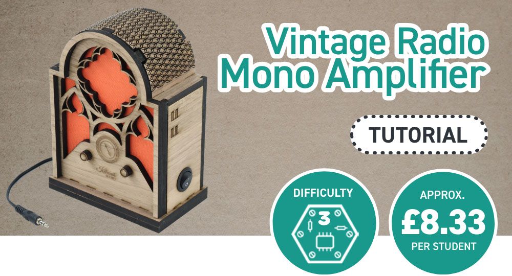
Based loosely on the appearance of a 1930s Cathedral Radio, this make utilises the Mono Amplifier Kit that comes with a status LED and switch, and swaps out the surface mounted switch for a round rocker switch that can be mounted to the outside for easier access. This make also covers the use of living hinges, which are a fascinating way to bend a solid sheet of material using a series of cuts.
This blog was was written by Emma and is one of the 6 included projects in the Book of Projects Volume 5. Background Image by Lazarescu Alexandra on Unsplash.
This make covers:

What did we use?
- 6mm American Black Walnut Veneered MDF (600mm x 400mm) (3246)
- B/BB Poplar Plywood (600mm x 400mm) (32213)
- Mono Amplifier Kit with Power Switch and Status LED (2173)
- 4 x 10mm Plastic Spacers (2333)
- 4 x 12mm M3 Pan-Head Screws (2311)
- 4 x 16mm M3 Pan-Head Screws (2339)
- 4 x 6mm M3 Pan-Head Screws (2309)
- 4 x M3 Hex Nuts (2315)
- 1 x SPST Round Rocker Switch (3407)
- Fabric
- PVA Glue
- Laser Cutter
- Soldering Equipment
- This DXF design file.
Note:
- The price may fluctuate slightly over time but was correct at the time of printing.
Step 1 – Check out the design files.
This DXF contains the design for this project. The diagram below shows you how to work with the file.
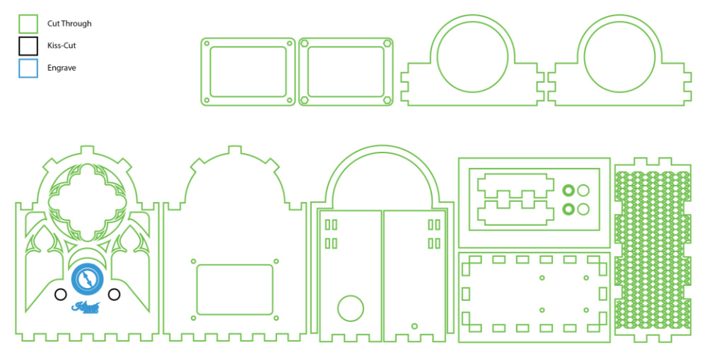
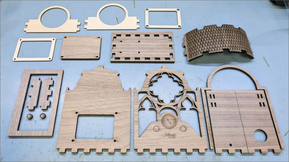
This design is in two parts: the four panels at the top are internal panels to be made from B/BB Grade plywood, and the rest on the lower part of the design were made from 6mm thick American Black Walnut. You can fit seven sets of the internal panels on a 600 x 400mm sheet, and the external panels can be fit two to a sheet.
The black lines should be kiss-cut (a cut that doesn’t go all the way through the material), then the blue lines should be engraved, and then lastly the green lines should be cut through all the way.
Step 2 – Laser cut the vintage radio.
Using the instructions in the diagram above, cut out the radio.
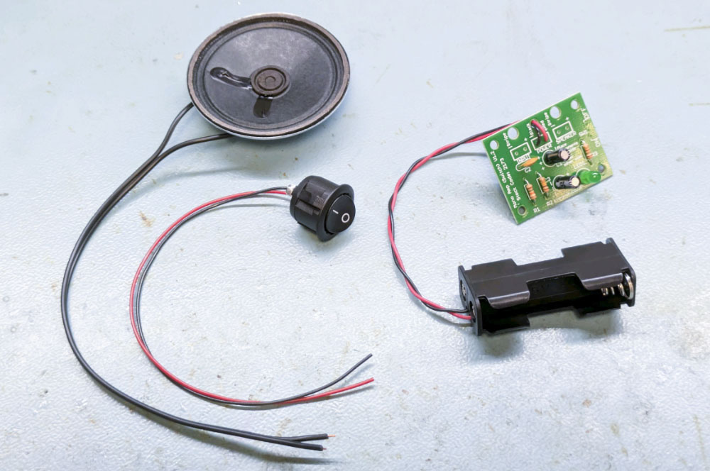
Step 3 – Assemble your Mono Amplifier Kit.
Assemble using these instructions most of the way, leaving the 3mm jack lead and the speaker detached from the board, and entirely skip adding the switch.
Attach two wires to an SPST Round Rocker Switch, one to each of the metal contacts on the back.
Step 4 – Finish assembling the kit.
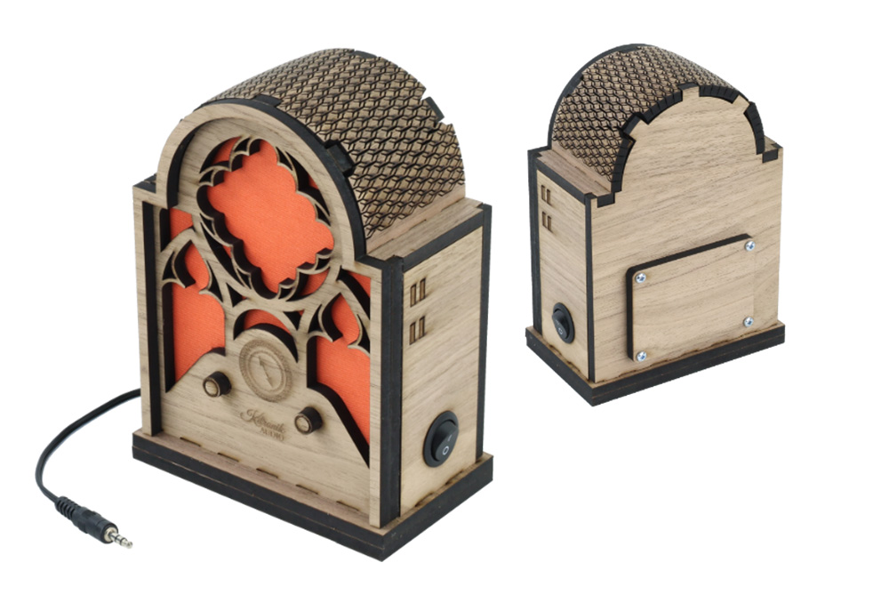
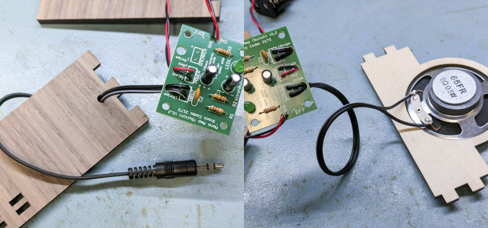
The rest of the assembly of the kit takes into account the panels through which the wires for the components need to be threaded before soldering. The switch needs to be pushed into the large round hole in one of the sides, the speaker wire needs to be threaded through the hole in one of the two internal panels with the large round holes, and the jack lead needs to be passed through the small hole in the other side wall.
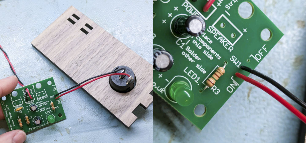
The switch will work a little differently to the original surface mount switch. Since we only have two wires now, you will want to solder them into the hole closest to the word “on” and the middle hole under the label SW1.
Note: make sure you pass the wires through the sides in the correct orientation – both sides need to be facing the same direction. Check photos later in these instructions for a visual reference!
Step 5 – Assemble the bottom of the radio.
Using PVA glue, attach the two sections of the bottom of the radio together as shown.
Please note that one side of the base protrudes outwards slightly – this is the front.
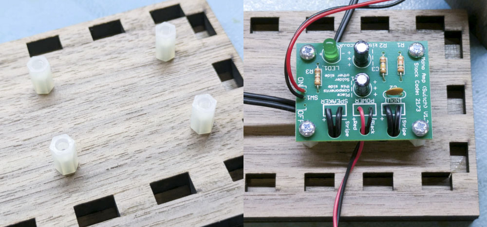
Step 6 – Mount the PCB
Using the M3 pan-head screws and spacers, mount the PCB to the base of the radio.
The spacers are attached to the base of the radio using the 12mm pan-head screws up through the holes in the base, and then the board can be screwed on top through the mounting holes using the 6mm pan-head screws. The board orientation doesn’t matter.
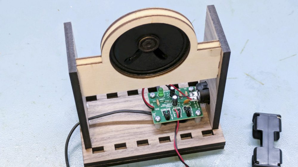
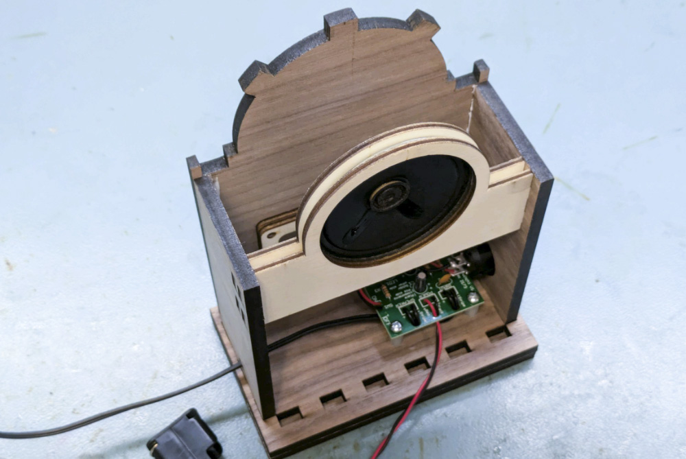
Step 7 – Raise the side walls, and mount the speaker.
Now you’ll want to sandwich the speaker between the two long panels with large holes, using the finger joints in them and the holes in the side walls to mount the speaker at the top of the enclosure, as shown in the image. Use a little PVA to secure the bottom of the side walls and the internal speaker mount panels in place.
Note: the speaker should be closer to and facing the front of the radio, which is marked
by the thicker edge on the base.
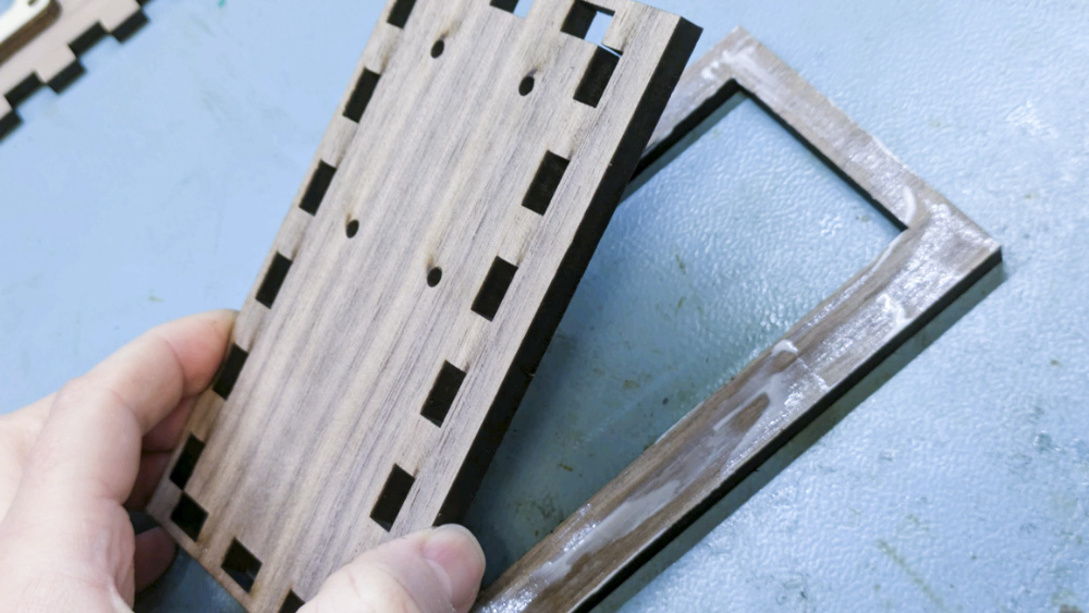
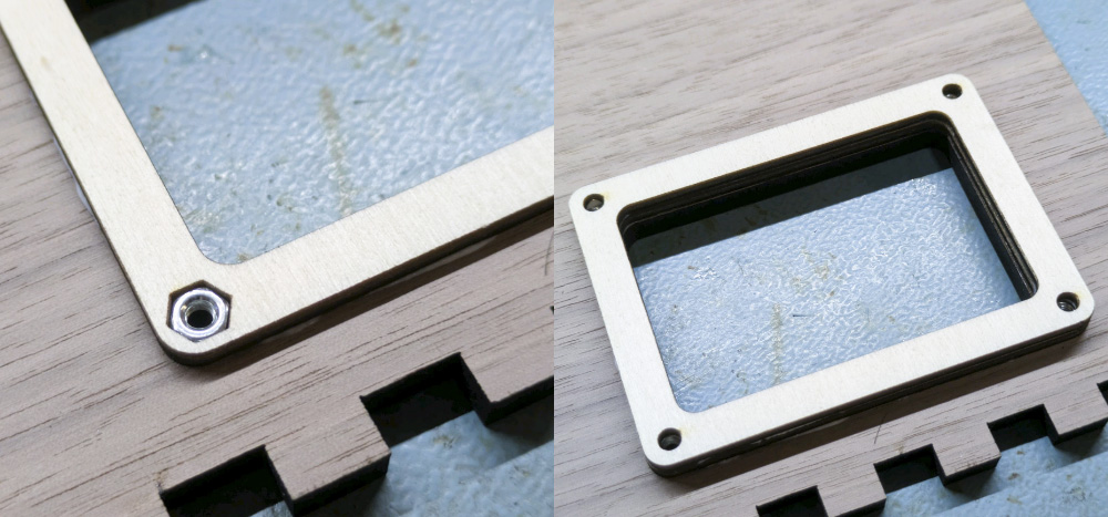
Step 8 – Create the access hatch.
There are two other internal panels – these encapsulate a hex nut in each corner of the access hatch so that it can be screwed on. Create this by gluing the panel with hexagonal corner holes directly onto the inside face of the back panel of the radio, aligning the holes in the middle. Then insert hex nuts into each corner, before gluing down the second panel with the smaller holes. This will hold the hex nuts in place.
Screw on the back panel using the 16mm pan-head screws.
Step 9 – Attach the back panel.
Slide the back panel of the radio – with the internal access panels facing inward – into the holes at the back of the radio. Use a little PVA in the finger joints to hold in place.
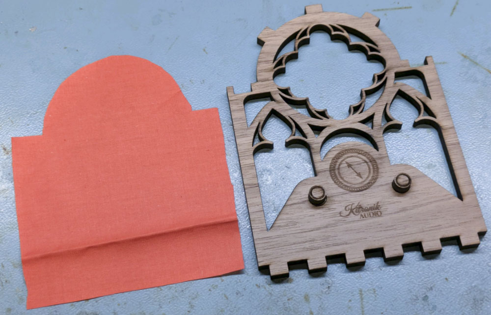
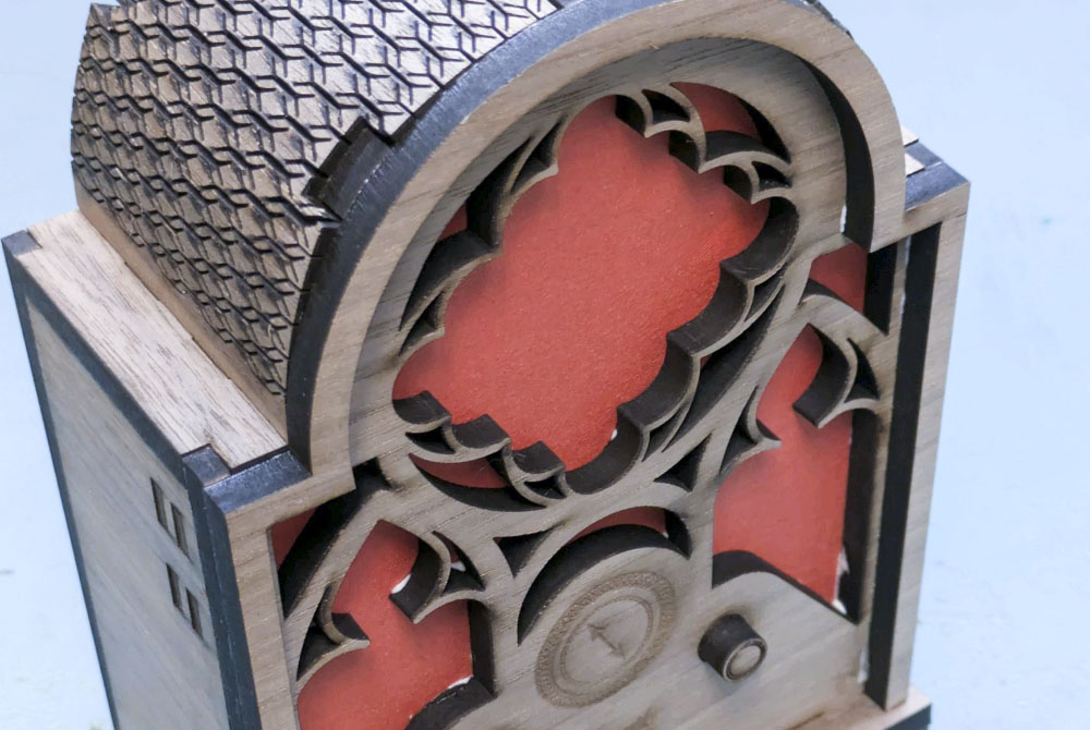
Step 10 – Construct the front of the radio.
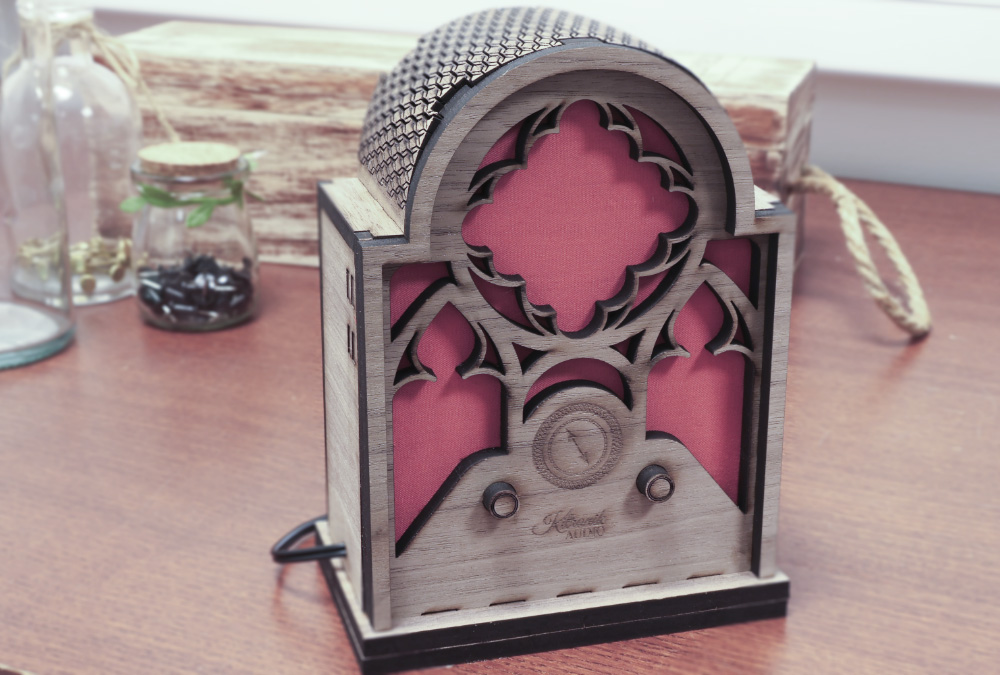
In this step we want to add the embellishments to the front panel of the radio before we mount it. This includes adding the small fake radio tuning knobs and, if you choose, some fabric to obscure the workings. This mirrors the use of acoustically transparent fabric in real cathedral radios – you could research this as part of your project!
Again, we used PVA glue to secure this all in place.
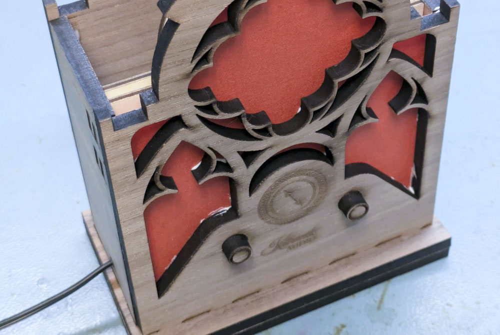
Step 11 – Attach the front panel.
Slide the front panel of the radio into the holes at the front of the radio. Use a little PVA in the finger joints to hold in place.
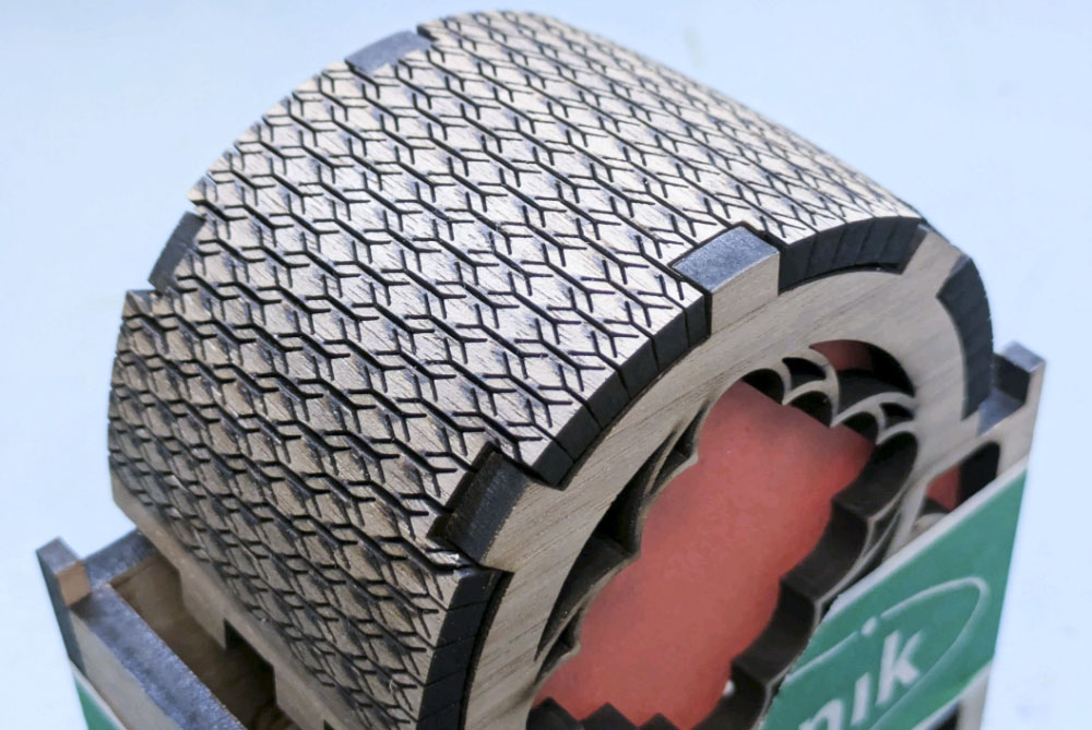
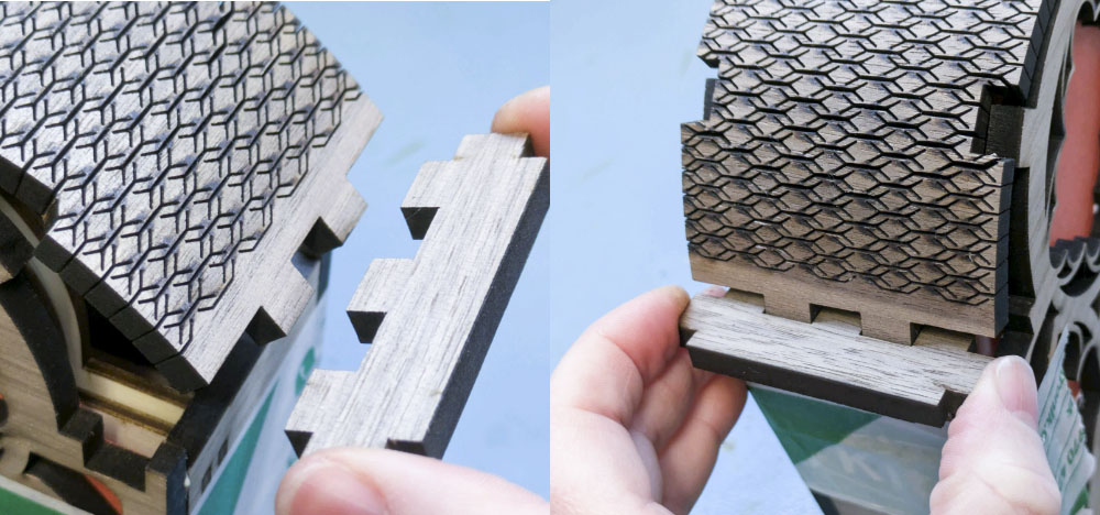
Step 12 – Attach the top of the radio.
The two small panels on either side lock the front, back, sides and curved top together, so can be a little tricky to get in, but will stop the top from springing back at all. This part demonstrates wonderfully the flexibility you can give to an otherwise rigid material using a living hinge. The strategic cuts in the top panel allow you to bend it around the curve, where you should use a little PVA to affix it in place, along with clamping it to make sure it doesn’t spring back while it dries.
The two small panels on either side lock the front, back, sides and curved top together, so can be a little tricky to get in, but will stop the top from springing back at all.
Step 13 – Glue on the decorative moulding.
This part mirrors the decorative moulding on cathedral radios – you can simply glue it on now that everything else is in place.
Step 14 – You’re finished!
Open up the back panel, add 2 AA batteries, plug in the jack and fire up some tunes! We recommend looking for some real 1930s classics to fit the vibe.