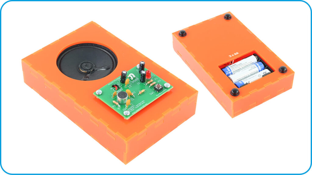
This is a simple example of an enclosure that you could make based on the Record Playback Kit V2.0, an update released in Feb 2026 that modernises and improves on the original kit! Follow along with Emma’s detailed instructions and make your own, or use them to deliver engaging design and fabrication lessons in the classroom.
*Price per student calculated based on exVAT prices for 60 students, at one kit each and fitting 3 enclosures per 600 x 400 mm Orange Value Acrylic sheet. Background Image by Pawel Czerwinski on Unsplash.
This Make Covers:

What did we use?
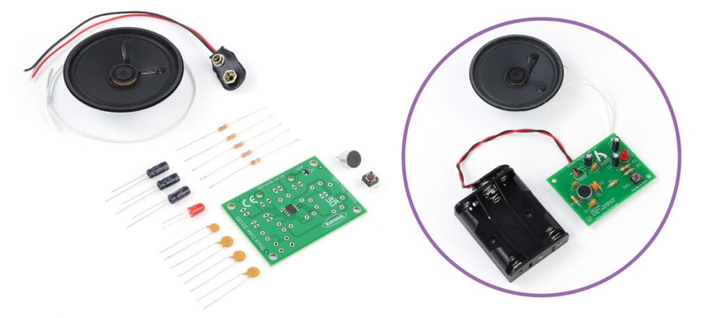
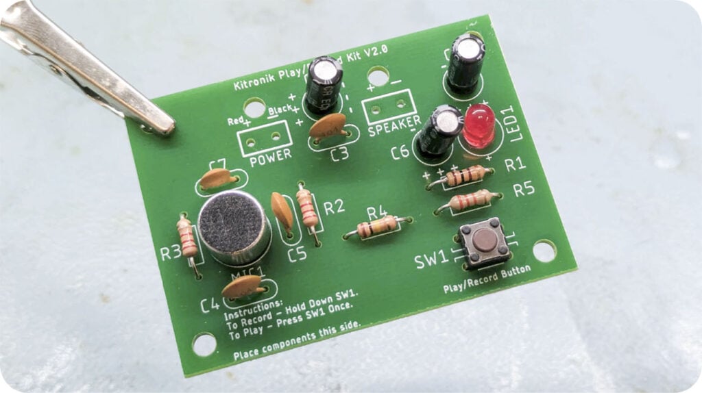
- Record Playback Kit V2.0 (21102)
- Orange Value Acrylic (43192)
- 4 x M3 10mm Pan-Head Screws (2310)
- 2 x M3 6mm Counter-Sunk Screws (2312)
- 4 x M3 Nylon Nuts (2330)
- 6 x M3 Hex Nuts (2315)
- Superglue
- A Laser Cutter
- (Optional) Rubber feet
- This design file.
Step 1 – Check out the design files:
This DXF contains the design for this project. The diagram below shows you how to work with the file.
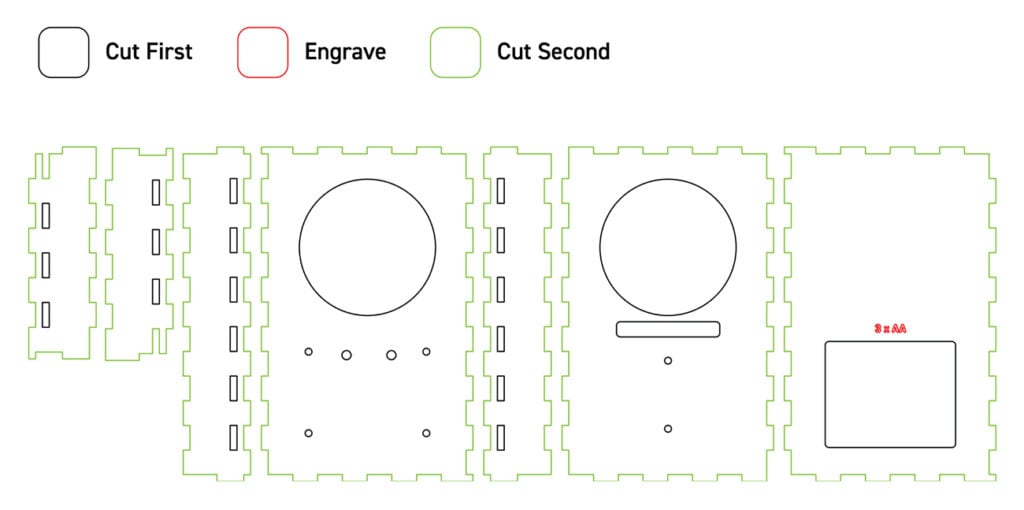
This design can be fit three to a sheet of 600 x 400mm material. The red outlines are engraved to provide a battery label, then the black lines should be cut first in order to prevent shifting, and then after that the green lines should be cut.
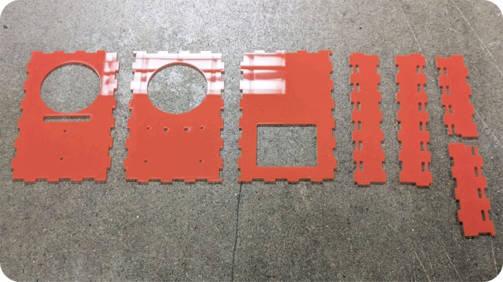
Step 2 – Laser cut the enclosure:
As specified in the diagram above, cut out the enclosure panels.
Step 3 – Solder the kit together most of the way:
Using these instructions, solder all the components onto the board, excluding the power and speaker wires. These will be attached later, around the enclosure.
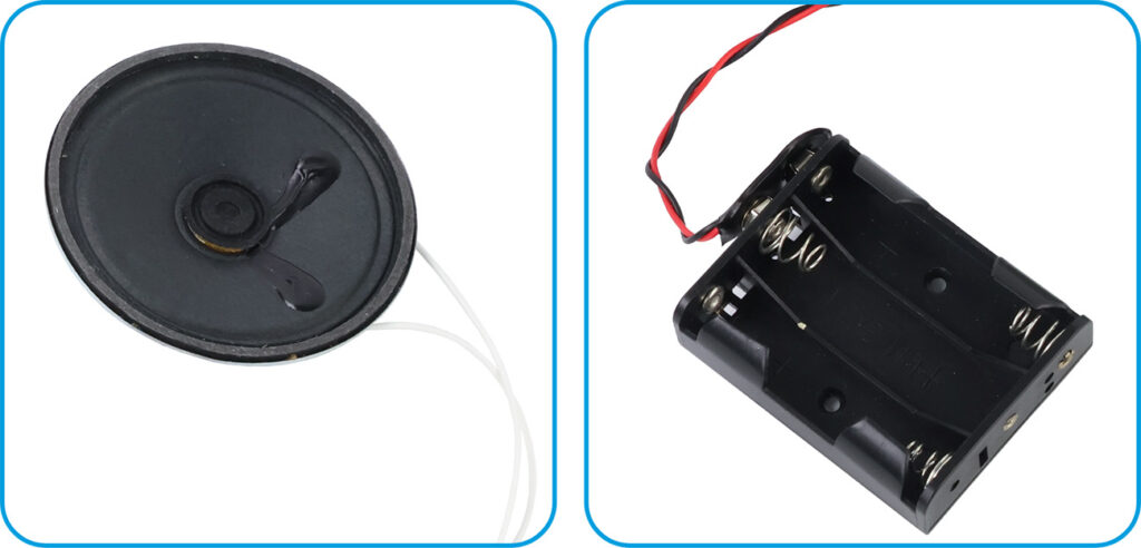
Step 4 – Add wires to the speaker and battery box:
As per the instructions, use two lengths of the included wire and solder them to the speaker, and then attach the battery clip to the battery box.
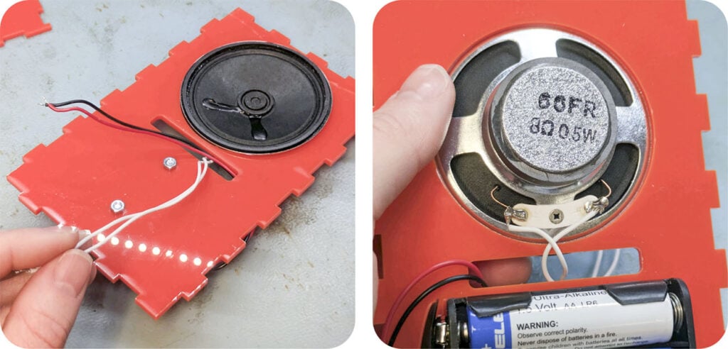
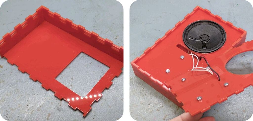
Step 5 – Arrange the speaker onto the internal panel:
The panel shown with the long horizontal hole beneath a large circular hole sits inside the enclosure to support the speaker and battery box. Screw the battery box onto the back of the panel using two M3 6mm counter-sunk screws and two M3 nuts, then settle the speaker into the round hole, with the wires at the back as shown. Then feed all of the wires forward through the long rectangular hole.
NOTE: Please make a note of the orientation of the panel in the images, making sure the finger joints around the edge are the same way around as ours. If they aren’t, you simply need to flip the panel over.
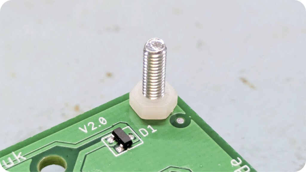
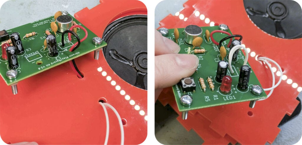
Step 6 – Attach screws and spacers to the PCB for mounting:
Attach four M3 10mm pan-head screws and four nylon nuts to the board through the mounting holes. The nuts are acting as a small spacer.
Step 7 – Solder the speaker and battery wires to the PCB through the front panel:
The front panel will sit on top of the internal panel, sandwiching the speaker in place. Feed the wires through the two most central small holes in the panel as shown, and then feed the wires up through the relevant mounting holes on the PCB and solder them in place.
NOTE: Correct orientation for the front panel will mean the finger joints will line up with those on the internal panel.
Step 8 – Mount the PCB onto the front panel:
Push the screws on the PCB through the four holes in the front panel, then use four M3 hex nuts to secure the board in place.
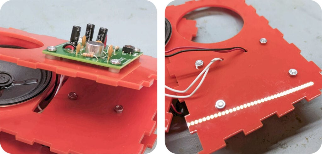
Step 9 – Build the rest of the enclosure around the kit.
Using superglue sparingly to secure the finger joints, build the side panels onto the back of the enclosure. Make sure to add the internal panel as you go, which slots into the holes in the middle of the side panels.
Step 10 – Affix the front panel, and you’re done!
The last step is to lightly glue the finger joints to secure the top panel onto the rest of the enclosure, and then you’re done! Optionally, if they’re available to you, we recommend adding rubber feet as a protective non-slip solution.