Resistors
Functionality
A resistor is a device that opposes (or limits) the flow of electrical current in a circuit. The bigger the value of a resistor the more it opposes (or resists) the current flow.
The amount of current that can flow through a resistor is given by the formula:
Current (in amps) = Voltage across the resistor / Resistance of the resistor (in Ohms).
The value of a resistor is given in Ω (ohms) and is often referred to as its ‘resistance’.
Resistors are available in different values. The bigger the resistance, the more it opposes the current that flows through it.
Circuit Symbols
 |
The symbol to represent a resistor on a circuit diagram is a rectangle, as shown left. |
 |
The symbol to represent a variable resistor on a circuit diagram is a rectangle with an arrow point to it, as shown left. |
Identifying Resistor Values

The value of the resistor is indicated by a number of colour bands printed on the side of the component.
Capacitors
What is a capacitor?
 |
A capacitor is a component that can store electrical charge (electricity). In many ways it is like a rechargeable battery. A good way to imagine a capacitor is as a bucket, where the size of base of the bucket is equivalent to the capacitance (C) of the capacitor and the height of the bucket is equal to its voltage rating (V). The amount the bucket can hold is equal to the size of its base multiplied by its height, as shown by the shaded area. |
Filling a capacitor with charge

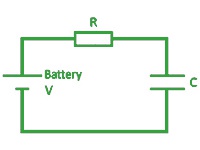
When a capacitor is connected to an item such as a battery, charge will flow from the battery into it. Therefore the capacitor will begin to fill up. The flow of water in the picture above left is the equivalent of how the electrical charge will flow in the circuit shown above.
The speed at which any given capacitor will fill depends on the resistance (R) through which the charge will have to flow to get to the capacitor. You can imagine this resistance as the size of the pipe through which the charge has to flow. The larger the resistance, the smaller the pipe and the longer it will take for the capacitor to fill.
Emptying (Discharging) a capacitor
 |
Once a capacitor has been filled with an amount of charge, it will retain this charge until it is connected to something into which this charge can flow. The speed at which any given capacitor will lose its charge will, like when charging, depend on the resistance (R) of the item to which it is connected. The larger the resistance the smaller the pipe and the longer it will take for the capacitor to empty. |
Diodes
Functionality
Diodes let current flow in one direction, but stop it from flowing in the other. They are like a one way valve. A lot of electronics, particularly integrated circuits don’t like being connected up the wrong way around and can be permanently damaged.
Diodes can be used to protect electronics from people connecting the power supply or battery up the wrong way around.
They are also used in almost every mains operated electronic product that is more complicated than a light bulb. The mains sockets provide 240 volts AC. The AC stands for alternating current, which means it switches from being positive to being negative 50 times a second. Electronic circuits require DC (direct current), which does not change. A diode can be used to stop the negative parts of the AC power, leaving just the positive section. A big capacitor placed across the supply after the diode will smooth out the power (See below). Often four diode are used together to give a smoother supply by keeping the positive parts and inverting (changing) the negative sections into positive.
Schematic Symbol
| The symbol for a diode is an arrow with a line across the end of the arrow. The arrow shows the direction that current will flow. The component has a band on one end so it can be put into the circuit the right way around. The band on the part corresponds to the line on the end of the arrow on the schematic symbol. |  |
Values
Diodes don’t have a value, but they do have a maximum current that they can take. This is not printed on the part, however a number, which identifies the part, will be printed on it. This part number can be used in a catalogue to find out what the maximum amount of current the diode can handle is.
 |
Unregulated mains electricity | |
 |
Positive parts after the diode, shown right. |  |
 |
Positive parts after the diode and smoothing cap, shown right. |  |
Transistors
Functionality
A transistor in its simplest form is an electronic switch. It allows a small amount of current to switch on or off a much larger amount of current. There are two types of transistor, NPN and PNP, the different order of the letters relate to the order of the N and P type material used to make the transistor. Both types are available in different power ratings from signal diodes through to power diodes. The NPN transistor is the most common of the two and the one examined in this sheet.
The diode has three legs, these are the base, collector and the emitter. The emitter is always connected to 0V and the electronics that is to be switch on is connected between the collector and the positive power supply. The base of the transistor is used to switch current through the collector and emitter. When the base is between 0V and 0.7V it is switched off and above 0.7V it is switched on allowing the current to flow from the collector to the emitter. A resistor is normally placed between the output of the integrated circuit (IC) and the base of the transistor to limit the current drawn through the IC output pin.
Schematic symbolThe symbol for an NPN type transistor is shown to the right along with the pins being labelled. |
 |
Values
Transistors don’t have values, but they do have different current ratings. The style of the package also changes as the current rating goes up. Low current transistors come in a D shaped plastic package, whilst the higher current transistors are produced in metal cans that can be bolted on to heat sinks so they don’t over heat. The D shape or a tag on the metal can is used to work out which pin does what. All transistors are wired differently so they have to be looked up in a catalogue to find out which pin connects where.

Download a pdf version of this page here ![]()
Learn more about the author read more » read more »