Experiment 8 from the Inventors Kit for Arduino. In which we explore wind power. Included in this resource are code downloads, a description of the experiment, and also a video walkthrough. It provides additional help and is not meant to replace the documentation that ships with the kit.  Arduino is an open-source code-able electronics platform. The boards can process inputs from many sensors, and also control outputs such as LEDs and motors. The Arduino is controlled by the code with which it is programmed. This code is written in the Arduino programming language, using the Integrated Development Environment (IDE). Once complete, the code is easily transferred to the board using a simple USB lead.
Kitronik Inventors Kit for Arduino Exp 8 Wind Power:
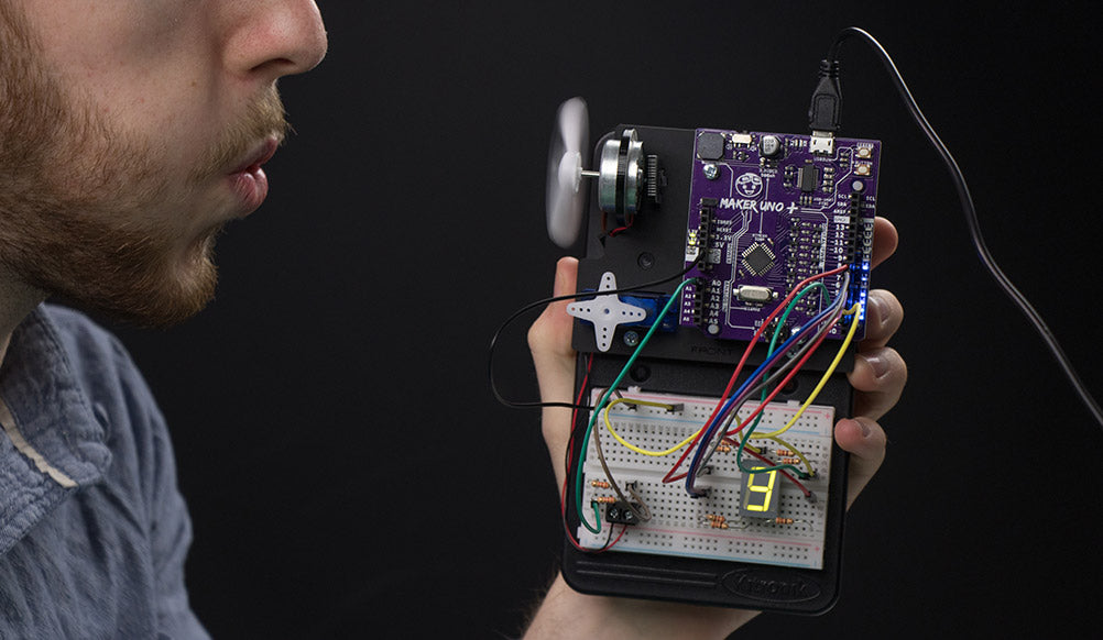
Wind turbines convert the kinetic energy of air into electrical power. In this experiment, the motor and also the fan are used in reverse to generate a voltage which can be measured and displayed by the Arduino using a seven segment display. The aims of this experiment are:
- To generate a voltage by blowing on a fan blade to spin a motor.
- And to measure this voltage by using an analog input pin on the Arduino.
- Also, to display the voltage generated using a seven segment display.
Video Walkthrough:
Exp 8 Code:
Either open a new Sketch (File > New) then create the following code by typing in the editor window. Or, click the open code button in the editor to open the code in the online editor.
Inventors Kit Extra Resources:
Each of the ten experiments has been designed to ease you into coding and also physical computing for the Arduino. The experiments have been chosen to cover the key concepts of physical computing and they also increase in difficulty as you progress. If you are new to this, even the least complex examples can be quite challenging. With this in mind, we created walkthrough videos for each of the experiments. Our presenter talks you through the circuit in a way that backs up the information given in the booklet but in a style that some might find easier to absorb. As well as having a video walkthrough, each page also contains the code. Although it is always good to tackle the code yourself, it can be handy for testing your circuit. The code has been heavily commented as an extra learning resource. To get the most out of the experiment, once you’ve tested your circuit have a go at coding the experiment from scratch. Follow the links in the table below:
| Exp No#. | Experiment Name. |
|---|---|
| Digital Inputs & Outputs. | |
| Light Sensor & Analog Inputs. | |
| Dimming an LED using a potentiometer. | |
| Using a transistor to drive a motor. | |
| Control a servo with a potentiometer. | |
| Setting the tone with a piezo buzzer. | |
| Using a seven segment display. | |
| Exploring wind power. | |
| Capacitor charge circuit. | |
| Using an RGB LED. |