Using a Light Sensor and Analog Inputs from the Kitronik Inventors Kit for the BBC microbit. We’ve included the entire experiment as a free example of the great practical experiments that are contained within the Inventors Kit. Learn how to build the circuit and how to code the microbit to control the circuit.  You can complete this ‘Using A Light Sensor And Analog Inputs’ experiment with or without the Inventors Kit. If you do not have the Kitronik Inventors Kit you will have to source all of the required components separately, a full list of the things you will need can be found below. NOTE: This is an updated version of this experiment. The Inventors Kit versions prior to V1.7 featured an LDR in place of the phototransistor featured here. You can access the LDR version of this experiment here: Using an LDR and analog inputs.
This Experiment Requires:
- A BBC micro:bit.
- 1 x Phototransistor.
- A 10kΩ Resistor.
- 3 x M/F Jumper Wires (If using the Prototyping System).
- 3 x Crocodile Leads (If not using the Prototyping System).
The Aims Of This Experiment Are:
- To use a phototransistor as a sensor.
- The, to perform an analog reading from the phototransistor via input pin P0.
- Finally, to set a light threshold to decide whether to display a sun or a moon on the LED matrix.
Experiment 2 Video Walkthrough:

Experiment 2 – Using a Light Sensor and Analog Inputs:
A phototransistor is an electrical component with unique properties. A phototransistor is a transistor that reacts to light by changing how well it conducts electricity. Particles of light are also known as ‘photons’, hence the name phototransistor. The more light that shines on the phototransistor the more it is able to conduct In this experiment a phototransistor is used along with a resistor to form a potential divider. When used in this configuration it gives a voltage that changes depending on the light level. A microcontroller such as the BBC micro:bit can read this (analog) voltage allowing a program to react to different light levels. This experiment will explain how to use a phototransistor and take an analog reading.
Creating The Code Using The Microsoft MakeCode Editor:
The image below shows the blocks in the MakeCode editor that will be used in this experiment.  The embedded editor below shows an example of how to write the code for this experiment using the MakeCode Editor.
If you’re having difficulty producing your own code for this experiment, you can download the code directly from the embedded editor above. You will also find the links for the code towards the end of this article.
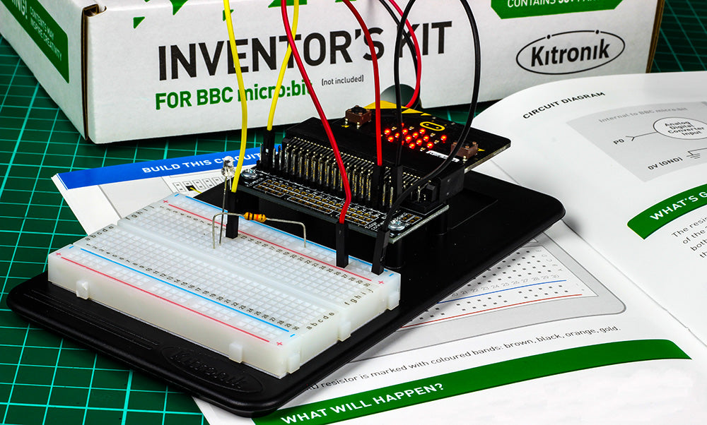
Building This Circuit On The Prototyping System:
It is possible to build this circuit using the Prototyping System for the BBC micro:bit and the components listed at the top of the page, you can follow the diagram below. 
What Will Happen:
To begin with the BBC micro:bit should display a sun image. If you cover the phototransistor with your finger to put it into darkness, it should show a ‘moon’ image. When uncovering the phototransistors and allowing light to shine onto the phototransistor, the BBC micro:bit should display the ‘sun’ image.
Building This Circuit With Crocodile Leads:
If you don’t have the Kitronik Inventors Kit for the BBC micro:bit or the Prototyping System you can still build the light sensor and analog inputs circuit using the circuit diagram for reference and Crocodile Leads to join the components together. You can see an example of this in the picture below. 
Circuit Diagram:

What’s Going On (How does it work?):
The resistor labelled R1 and the phototransistor are in series so they divide the 3V across them. As more light shines on the phototransistor this allows more current to flow and then increases the voltage towards 3V. When there is less light, the resistor helps pull the voltage down to 0V. The analog read function measures the voltage on the selected pin and converts it into a value between 0 and 1023. Firstly, if the voltage on pin P0 is 0V then this value will be 0. Also, if the voltage on this pin is the maximum of 3V then the value will be 1023. Finally, if the voltage on P0 is 1.5V the value will be 512. This being the voltage being divided in half. The pin P0 is read and the value is stored in the variable ‘light’. The ‘if’ statement then checks if the value stored in ‘light’ is greater than 200. This equates to a voltage of greater than 0.59V on pin P0. If this is the case then the LEDs in the pattern of a sun is displayed on the LED matrix, otherwise, the moon pattern is displayed.
Code Downloads:
The light sensor and analog inputs code examples below have been individually zipped and can be downloaded by clicking on your preferred option. Once unzipped you can either open the and edit the code in appropriate editor or place the HEX file onto your microbit*.
MakeCode Editor and Python Code Downloads:
- This code was created with the MakeCode Editor, download the HEX file here.
- This code was created with the Python Editor, download the HEX file here.
* – To place the unzipped HEX file onto your microbit, connect your microbit to your computer via USB and then open File Explorer (Windows). Your microbit should show up as a removable drive. Simply drag and drop your HEX file onto the microbit in file explorer and the file will be transferred. The power light on the back of the microbit will start to flash, once the flashing stops the microbit is ready to run your code.
All Kitronik Inventors Kit Resources:
| Exp No#. | Experiment Name. | Resource Type. |
|---|---|---|
| 1 | Say Hello to the BBC micro:bit. | Further Help. |
| 2 Pre V1.7 | Using an LDR and analog inputs. | Full Experiment + Further Help. |
| 2 V1.7 | Using a Light Sensor & analog inputs. | Full Experiment + Further Help. |
| 3 | Dimming an LED using a potentiometer. | Further Help. |
| 4 | Using a transistor to drive a motor. | Full Experiment + Further Help. |
| 5 | Using the accelerometer to control motor speed. | Further Help. |
| 6 | Setting the tone with a piezo buzzer. | Further Help. |
| 7 | Wind Power. | Full Experiment + Further Help. |
| 8 | Making a game using the compass. | Further Help. |
| 9 | Capacitor charge circuit. | Further Help. |
| 10 | Using an RGB LED. | Further Help. |
| 11 | Making a pedestrian crossing. | Full Experiment + Further Help. |
| 12 | Making a random dice. | Full Experiment + Further Help. |
Using A Light Sensor And Analog Inputs Booklet Errata:
 The current version of the BBC micro:bit booklet is 1.3. If you have version 1.1 then please see below for corrections made to the current version.
- On page 19 there is a box describing which blocks you need for this experiment.
- We incorrectly listed an IF DO ELSE block. This should be an IF DO block.
- You then need to click the cog icon to change the ‘if do’ block into an ‘if do else’ block by dragging the ‘else’ into the ‘if’ loop as shown above.
