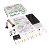
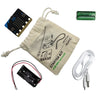
This Experiment Requires:
- BBC micro:bit. x 1
- Red 5mm LED. x 2
- Green 5mm LED. x 2
- Yellow 5mm LED. x 2
- Orange 5mm LED. x 1
- M/F Jumper Wires. x 6
- M/M Jumper Wires. x 6
The Aims Of This Experiment Are:
- To make a dice using seven LEDs.
- To use the ‘Pick Random’ number block.
Experiment 12 Video Walk Through:
Experiment 12 Making A Random Dice:
This experiment will create a random electronic dice. The numbers the dice display will be created by seven LEDs on the breadboard, arranged in the layout seen on the six sides of a real dice. The code will make use of the ‘pick random’ block to generate a random number when button A is pressed on the BBC micro:bit. Depending on the value of this random number the relevant LEDs on the breadboard will be lit up.The Microsoft MakeCode Editor For The BBC micro:bit:
This experiment is created using the Microsoft MakeCode Editor. The Microsoft MakeCode Editor is a drag and drop visual editor that provides a simple introduction to programming. Blocks snap together to build programs and are grouped by the type of function they do. When a group is selected, the commands in that group are shown and can be selected.Create The Following Code:
If you're having difficulty producing your own code for this experiment, we've created the code for you that you can download straight from the embedded editor above.Building This Circuit On The Prototyping System:
It is possible to build this circuit using the Prototyping System for the BBC micro:bit and the components listed at the top of the page. Once you have sourced the required parts you can follow the diagram below.What Will Happen?:
Press and release button ‘A’ on the BBC micro:bit. A random number should now be displayed on the LEDs on the breadboard. Try pressing the button a number of times to make sure all six of the possible numbers can be displayed.Circuit Diagram:
What's Going On?:
Firstly the ‘on button A pressed’ block is used to determine when button A has been pressed on the BBC micro:bit and a new dice number needs to be calculated and displayed. Pressing the button causes the ‘item’ variable to be loaded with a random number between zero and five, which is generated by the ‘pick random’ block. The ‘item’ variable then has one added to it so that it will be in the range one to six (one of the numbers on a dice). Once the random number between one and six has been calculated all of the LEDs are turned off (to clear the last number) and the ‘item’ variable is then checked by an ‘else if’ block and this causes the LEDs needed to display that number to be turned on. The relationship between the number that is to be displayed on the dice, the LEDs that need to be lit up, and the pins that control them, are shown in the table on the opposite page. So, for example, if the number 3 was to be displayed on the dice, this would require LEDs 1, 2 and 3 to be lit. These are controlled by pins P0 and P1 (P1 controls LEDs 2 and 3). As the cathode of the LEDs are permanently connected to 0V (GND), the LEDs are turned on by taking the associated BBC micro:bit pin high. This creates a voltage across the LED(s) and turns it/them on.Code Downloads:
The code examples below have been individually zipped and can be downloaded by clicking on your preferred option. Once unzipped you can either open the and edit the code in appropriate editor or place the HEX file onto your microbit*.MakeCode Editor & Python Code Downloads:
- This code was created with the MakeCode Editor, download the HEX file here.
- This code was created in MicroPython, get the code here.
Legacy Editors Code Downloads:
NOTE: The legacy editors will disappear at some undisclosed point in the future. The code can still be placed on a microbit and will run regardless but you won't be able to use an editor. When that happens, switch to using one of the currently supported editors. We've already made the switch as the new editors are better and more fully featured.- This code was created with the Blocks Editor, download the HEX file here.
- This code was created with the Touch Develop Editor, download the HEX file here.
Extension Tasks:
- Can you make the dice work using the ‘On Shake’ command?
- Can you make the LEDs flicker while the button is being pressed?
Kitronik Inventors Kit Resources:
| Exp No#. | Experiment Name. | source Type. |
|---|---|---|
| 1 | Say Hello to the BBC micro:bit. | Further Help. |
| 2 Pre V1.7 | Using an LDR and analog inputs. | Full Experiment + Further Help. |
| 2 V1.7 | Using a Light Sensor & analog inputs. | Full Experiment + Further Help. |
| 3 | Dimming an LED using a potentiometer. | Further Help. |
| 4 | Using a transistor to drive a motor. | Full Experiment + Further Help. |
| 5 | Using the accelerometer to control motor speed. | Further Help. |
| 6 | Setting the tone with a piezo buzzer. | Further Help. |
| 7 | Wind Power. | Full Experiment + Further Help. |
| 8 | Making a game using the compass. | Further Help. |
| 9 | Capacitor charge circuit. | Further Help. |
| 10 | Using an RGB LED. | Further Help. |
| 11 | Making a pedestrian crossing. | Full Experiment + Further Help. |
| 12 | Making a random dice. | Full Experiment + Further Help. |
©Kitronik Ltd – You may print this page & link to it, but must not copy the page or part thereof without Kitronik's prior written consent.


