In this tutorial we are going to look at how to control a servo using the microbit via an Edge Connector Breakout Board for the BBC micro:bit. It’s super simple to set up and requires very few parts.

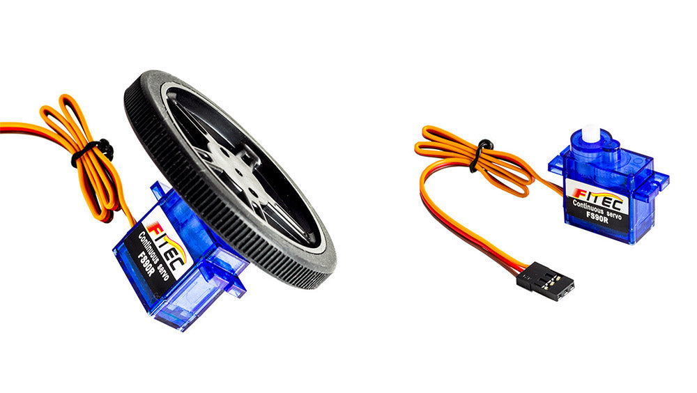
For this tutorial we used the 180 Mini Servo, this servo is great for this application. We have used this particular servo for several different projects as it is small and has a decent amount of torque.
Note:
Problem: Although we have used the BBC micro:bit as a power source for the servo, in this and other projects, this isn’t the ideal method. This has to do with the maximum amount of current that the BBC micro:bit can handle, using the BBC micro:bit to supply power to a servo has you very close to this limit. Solution: Using a battery pack to provide power directly to the servo and only using the BBC micro:bit to supply the control signal to the servo is the best way to protect your BBC micro:bit from harm and to ensure that you are getting the full amount of torque from the servo.
Level Of Difficulty:
- Easy.
Parts List:
- 1 x BBC micro:bit.
- 3 x M/F Jumper Wires.
- Either 1 x Prototyping System for the BBC micro:bit.
- 1 x 180 Mini Servo.
You Will Also Need:
- An Internet browser.
- A USB cable to connect the BBC micro:bit to the computer.
Possible Uses:
We recently posted an article submitted by Thomas Stratford in which he shared his process for making a pedestrian crossing with the BBC micro:bit. If you wanted to add a little extra complexity to your project you could use a servo as a level crossing barrier.
Using The BBC micro:bit To Control A Servo Process:
- 1 – Connect the Servo to the Breakout board.
- 2 – Write/download the code.
- 3 – Put the code onto the BBC micro:bit and test.
- 4 – Troubleshoot any issues.
Step 1 Connecting The BBC microbit To The Servo:
The servo has a three wire connector. The brown wire is ground, the red wire is positive and the orange wire is the signal wire. The BBC microbit will send instructions to the servo from the P0 pin via the servo’s signal wire. Push the BBC micro:bit into the Breakout Board. Use the 3 x M/F Jumper wires to connect the Servo to the Breakout Board, the table below shows how the connections are made.
| BBC micro:bit Edge Connector Breakout Board | 180 Mini Servo |
|---|---|
| 3V Pin. | Red Wire. |
| GND. | Brown Wire. |
| P0 Pin. | Orange Wire. |
Note: This experiment can also be done without the Edge Connector Breakout board. In order to do this, you will need 3 x Crocodile Leads and you will need to cut off the Servo’s connector and strip the three wires. The connections in the above table remain the same if using this method, though you will be connecting the Crocodile Leads directly to the BBC micro:bit.
Step 2 Write The Code:
As you can see in the picture below, we produced two code examples to control a servo. This was just to illustrate that there is more than one way to get the job done.
Example 1:
In Code Example 1 we made use of both of the BBC micro:bit’s buttons. Button A makes the servo spin around one way and Button B returns it to its starting position.
Example 2:
In Code Example 2 we used button A on the BBC micro:bit to start the process, the servo then continues to move one way and then the other until the BBC micro:bit is either reset or its power source is disconnected.
Step 3 Download The Hex File To The BBC micro:bit And Test:
To Download: Choose your preferred option from the embedded editors above. Press the download link at the bottom of the embedded editor. The code will now download to the default download folder on your computer. Once you have downloaded the code from one of the links above, connect your BBC micro:bit to your computer via USB. Navigate to the file you downloaded in your downloads folder and drag it straight onto the BBC micro:bit in File Explorer (Windows). Once the .hex file is on the BBC micro:bit, press button A and the servo should move. If you used Code Example 1 pressing A will make the Servo move in one direction only. If you used code example 2, pressing button A will make the servo rotate one way and then the other until you press the reset button on the BBC micro;bit or disconnect it from the power source.
Step 4 Troubleshooting:
- Check that you have connected the servo to the breakout board correctly, refer to the table in Step 1 for guidance.
- Ensure that the M/F jumper wires are pushed into the servo connector securely.
- Note: If writing your own code, using a forever loop in favour of one of the above methods may result in the servo not receiving quite enough power to turn. You can get around this by using a dedicated 4.8v power supply to power the servo directly whilst still using the BBC micro:bit to provide the control signal.


