The Kitronik ZIP Halo for the BBC microbit incorporates 24 colourful ZIP LEDs. It also has an ‘extension’ connection point that allows extra ZIP LEDs to be connected and controlled by the Halo. This tutorial shows how simple and quick this is to do.  To do the following you will need a Kitronik Halo, a BBC microbit and also a ZIP LED variant such as the ZIP Circle, and the MakeCode Editor (previously known as the PXT Editor). This tutorial also requires a little soldering.
Adding Extra ZIP LEDs To Halo For The BBC microbit:
The image below shows the location of the connector for adding extra ZIP LEDs. This is a three-way connector. The pads (spaced at 0.1″ / 2.54mm) can be soldered to directly or instead can be used to connect pin headers if the extra ZIP LEDs don’t want to be permanently connected to the Halo.  Firstly these connections will need connecting to the corresponding connections on the extra ZIP LEDs. In this example, we will be using a ZIP Circle as shown below. There are four connecting points on the ZIP ring but we will only need to connect to three, as the GND connection is duplicated on the ZIP Circle.

The connections should be made (soldered) as follows:
| Halo. | ZIP Circle. |
|---|---|
| GND (Ground). | GND. |
| Vsw (Power). | +5V. |
| DOUT (Data). | DIN. |
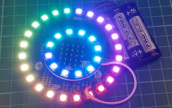
Once these have been done, the two boards will be connected as shown below.
So now we have the 24 ZIP LEDs on the Halo and 12 more ZIP LEDs on the ZIP Circle giving us 36 in total that can be controlled. When coding, the ZIP LEDs on the Halo come first and then follow on to the ones connected to the extension port. The following code gives a simple example of how to set the blocks up to control the 36 LEDs. A rainbow will be displayed and rotated (moved) across all 36 LEDs.
The results will look like this. 
Download:
- You can download the code for Halo here or directly from the embedded editor below:
Learn more about the author read more » If you don’t yet have a Halo or ZIP LED variant, you can grab what you need from the links below:


