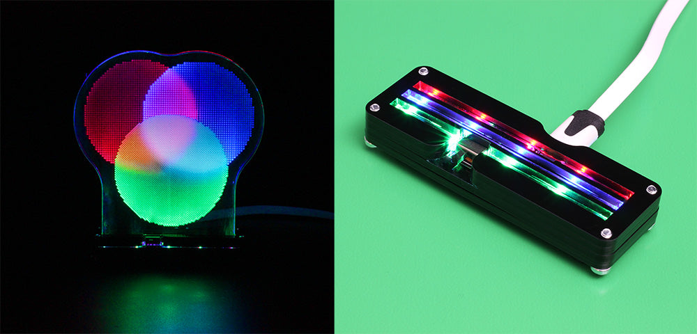
To demonstrate the basic concept behind our TriColour LED strip, and celebrate its launch, Emma made this edge-lit diagram so that you can experience Additive Colour Mixing yourself!
This would make a great classroom aid, or you could use it as a template from which to create your own designs! Why not try using colour mixing to create a full colour image?
Using Additive Colour Mixing in your Makes:
Additive colour mixing can be defined as follows:
The mixing of different wavelengths of light.
It is called “additive” because this process does not stop us being able to see any wavelengths, rather you are seeing all the involved wavelengths at once.
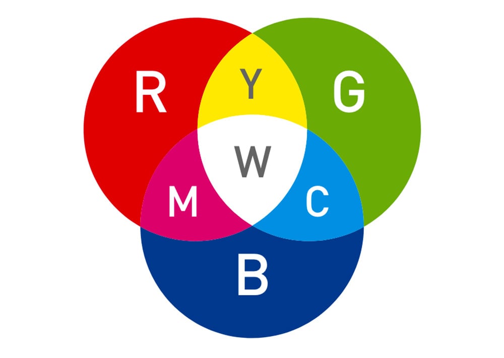
You can see this in practice in this diagram. The primary colours in additive colour mixing are RED, GREEN and BLUE, which is why products like addressable LEDs are often referred to as RGB. The secondary colours in additive colour mixing are CYAN, MAGENTA and YELLOW. All together, the three primary colours will make WHITE.
Subtraction colour mixing is the opposite. It involves the mixing of different pigments in mediums such as ink or paint.
How have we done it?
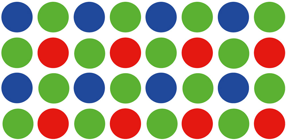
We have used a grid of circles that mimic a particular array of pixels called a “Bayer Filter”. This is also referred to as “RGBG” because of the layout of the colours, and it is usually used in cameras as light filters to produce full-colour images using additive colour mixing.
The Bayer Filter is arranged as per the image below, with twice as many green pixels as red or blue.
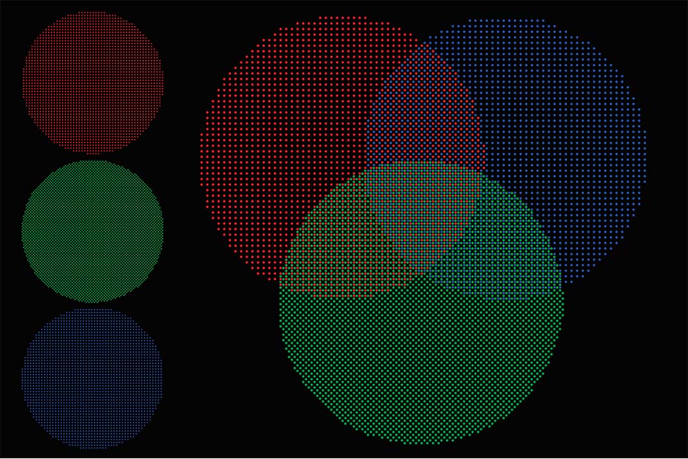
When arranged in a Venn diagram in which the overlapped sections are arranged as per the order above, you can see magenta, cyan, yellow and white appear:
How to Make the Edge-Lit Diagram:
We have made a diagram which uses the TriColour Board since it separates the RGB channels and makes it possible to use additive colour mixing.
We Used:
- This DXF.
- Kitronik TriColour LED Board.
- 3mm Black Acrylic.
- 3mm Clear Acrylic.
- 4 x 12mm M3 Pan Head Screw.
- 2 x 6mm M3 Countersunk.
- USB Cable.
Step 1 – Cutting the parts:
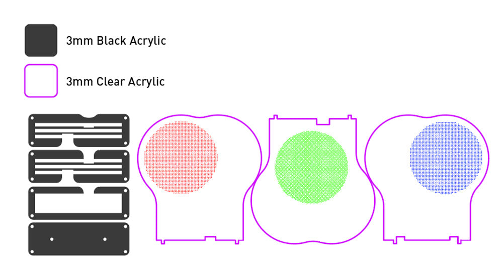
Check out the laser cutter file! It will look like outlines of the below diagram, which has been coloured to make it clear which materials each part needs to be cut from. The red, green and blue dots can be experimented with, you can either engrave them, kiss-cut them (shallow cut) or do both.
Step 2 – Assembling the Base:
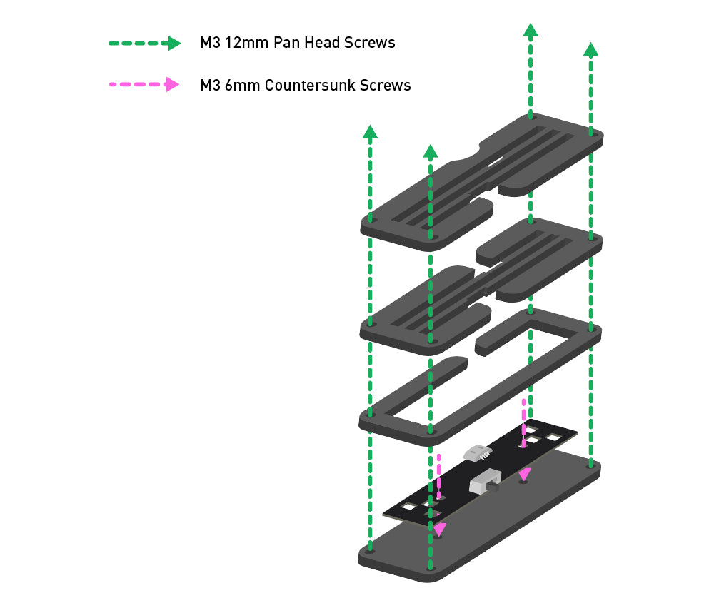
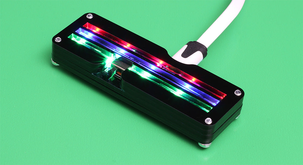
Build your base! The pieces cut from black acrylic can be assembled around the TriColour Board as per the diagram above. Once built, the base should resemble the image below;
Step 3 – Putting it all together:
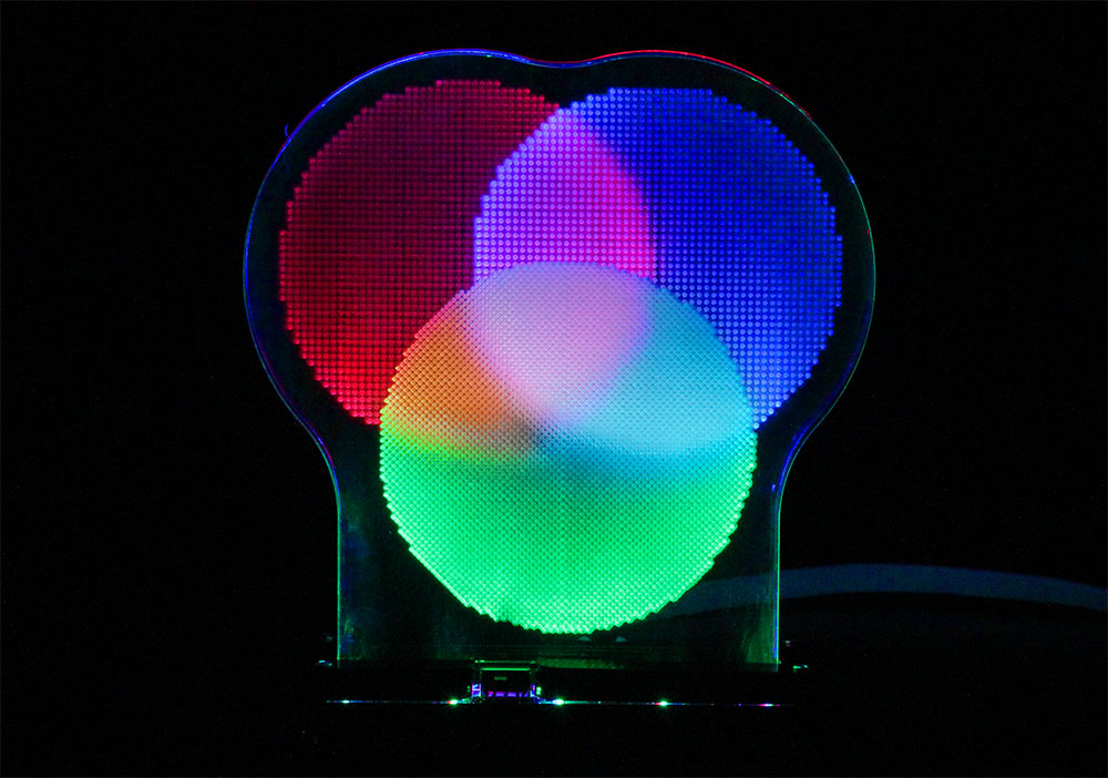
Place the clear acrylic designs into the correct slots – you can check the diagram in step 1 for which panel is which colour. Plug it in, turn it on, and you have your own edge-lit colour mixing diagram!