In this getting started guide for the Servo:Lite board for the BBC microbit we cover; attaching the Servo:Lite board to a microbit, the microbit pin assignments. Also, how to write code to control the lights on the board and the servos that are connected to it.

In addition, all of the code included in the guide is available to download. You can find the download button on each of the embedded code examples. We have also included links to other useful resources that we have produced for this board.
Getting Started With The Servo:Lite Board:
The Servo:Lite board for the BBC micro:bit is a simple board that allows you to easily connect and control low power servo motors (servo’s must be capable of operating at 3.3V) using the BBC micro:bit. It is connected to the micro:bit using five bolts. Connect two servos in standard configuration and it can drive up to 3 servos if the addressable ZIP LEDs aren’t needed.
It is powered by 3 AAA batteries which also supplies power to the BBC micro:bit. The board also features an On / off switch so when it’s not in use the batteries won’t drain.
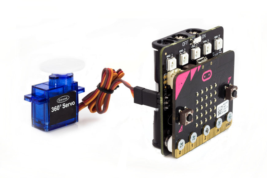
Attaching A microbit To The Servo:Lite Board:

The board has been designed so that the BBC micro:bit can be bolted to the front, using the supplied spacer and 5 M3x8 countersunk machine screws (See above image). Once connected, 3 x AAA can be inserted into the attached battery cage on the rear of the board. For more information please refer to the Servo:Light Datasheet.
Servo:Lite And microbit Pin Assignments:
| microbit. | Servo:Lite. |
|---|---|
| Pin 0. | ZIP LEDS. |
| Pin 1. | Servo 1. |
| Pin 2. | Servo 2. |
The board includes an integrated nut and bolt connection for the BBC micro:bit pins 0, 1, and 2. The above table shows how the microbits pins relate to the Servo:Light boards functions. For more detailed information please refer to the Servo:Lite Datasheet.
Connecting Servos To The Servo:Lite board:

The above image shows the positions of the Servo 1 and Servo 2 connections and it also indicates which pin is which for each connection. The image below shows the type of connector for the Kitronik range of servos and the wire colouring. If you are using a servo with different colourings than are shown below, please refer to the datasheet for that product.
When connecting the servo to the board, the brown wire would be connected to the top pin on the board and the orange signal wire would be connected to the bottom pin.

Writing Code To Control The ZIP LEDs:
In order to write code for the microbit to control the ZIP LEDs on the Servo:Lite board, we need to open a browser and go to the MakeCode Editor. If you are going to create the code yourself you will need to add the neopixel functionality to the editor. To do this, click on the Advanced option and then select ‘Extensions’ at the foot of the menu, the Neopixels option will be displayed and can be clicked on.
If you are dragging a hex file that contains neopixel blocks into the editor you will not need to Add Package as this is done automatically.
In the above example, we have two loops; the ‘On Start’ loop and the ‘Forever’ loop. In the ‘On Start’ loop we have created a variable to hold information about the ZIP LEDs; which microbit pin is being used to control them, how many LEDs there are, and what type of LEDs are being controlled. We then reduce the brightness a little and display a static rainbow pattern across the five ZIP LEDs.
In the ‘Forever’ loop we have three lines of code to animate the display by cycling each LED through the shown colours, the pause is to slow the cycling to speed so that our eyes can easily detect what is happening.
To grab the code, click the download button in the embedded editor above.
Writing Code To Control 2 Servos:
In the above code example; pressing button A rotates both servos by 180 degrees and pressing button B rotates them both back to their starting point. This code will allow you test that the Servo:Lite board is working and that the servos are behaving as expected. For more detailed coding guides, please refer to the further information links below.
To grab the code, click the download button in the embedded editor above.
Getting Code Onto The microbit:
Once you have downloaded the code to your computer, you will find the HEX file in your default download folder. Connect the microbit to your computer via USB. You will see it show up as a removable drive called MICROBIT. Pick up the file you downloaded and drop it directly onto the MICROBIT drive.
The light on the back of the microbit will begin to blink. Once it has stopped blinking the file will have finished transferring to the microbit and it is safe to either unplug the microbit or begin using the program.
The MakeCode Editor itself is also drag and drop. Allowing you to drop a HEX file into the editing area and it will open the file as a program allowing you to edit it.
Other Useful Information:
Links for the Servo:Lite Board Guides:
- Guide For Kitronik Custom Servo Blocks.
- Controlling 3 Servos With The Servo:Lite.
- Using Kitronik ZIP LEDs With The BBC microbit.
-
WS2812B Datasheet.

-
Servo:Lite Datasheet.
Links for :MOVE mini Guides:
- Controlling :MOVE mini With The microbit Radio.
- Adding Bluetooth Remote Control To :MOVE mini.
- Drawing With The :MOVE mini For The microbit.
- Automatic Headlights For :MOVE mini.
- Coding Indicators For :MOVE mini.
NeoPixels® is a registered trademark of Adafruit Industries LLC.