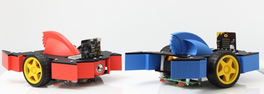
Way back when we first released our Motor Driver Board the microbit Block Editor only allowed digital write on the pins we used for controlling motors. This meant that motors had to be full on or off. Thanks to an update in the MakeCode editor you can now use PWM to control the motors and therefore the speed of your buggy.

What is PWM?
PWM or Pulse Width Modulation is a way of varying power into a pulsing signal. This lets us control how much power is sent to the motors by controlling the pulse.
When we talk about duty cycle we mean the portion of ‘on’ time compared to the total time; a low duty cycle corresponds to low power because the power is off for most of the time. Duty cycle is expressed in percent, 100% being fully on.

Writing The Code:
In this example, we’re going to use two microbits. One, the handset, is going to be used to send various commands to the other, the motor controller. We’re going to simply send a different value from the handset based upon if button A, B, or both are pressed. We’ll add an on shake command to bring the unit back to a stop. Using the MakeCode editor create this code or download it from the bottom of this guide.

On the motor controller, we’re going to see which number is received and apply a different frequency to make the motors go faster or slower. We’ll achieve this by using while/do loops.
If the received number is 0 we’ll set all pins to 0. If the received number is 1 we’ll set pin 0 and pin 8 to 300 (analogue) and leave P16 and P12 at 0. By increasing the values of pin 0 and pin 8 (up to 1023) we increase the speed, so we’ll add options for received number 2 and 3 as you can see below.
As you can see from the code we are using two different types of block to send power to the motors. The digital write and also the analog write. Behind the analog write block is a PWM pulse. Also, behind the digital write is an on/off command or full power/no power command.
Using the MakeCode editor create the code shown below. You can also download it from the bottom of this guide.
In Action:
As you can see from this quick video the buggy goes through three different speed cycles as we change the options on the handset.
New Blocks:
To make it even easier for you, we’ve created an Extension that lets you add our Motor Driver blocks to the editor.
Click cog in the top right of the Editor. The select Extensions from the menu and it will open the extensions window. Type Kitronik into the search bar and enter on your keyboard. The extensions window should now appear as shown below.

Then, select the Motor Driver blocks and the code blocks will now be available to us in the editor.
Note: We used this for our line following buggy in the video above but we did swap the wires around on the motor to set the buggy in line with “forward” in the block as can be seen below. Note: The blocks go from a speed of 0 to 100, not 1023 as with an analogue pin write.
To conclude, download the handset code here and the motor controller code here.


