

Buy locally from a partner
Bundled options
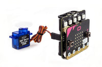
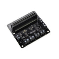
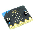
Motor driver board plus BBC micro:bit
 +
+
Description
| Attribute | Value |
| Operating Voltage (Vcc) | 3V to 10V. |
| Number of motor channels | 2 (2 motors with forward + reverse control, controlled by P0, P8, P12 & P16). |
| Digital only inputs | 2 (button A / B) |
| Digital or analog input / output pins (P1 & P2) | 2 (P1 & P2) |
| Typical motor output Voltage (Vm) @ 1.5A output per channel | Vm = Vcc – 0.3V. |
| Max Current per motor channel | 1.5A. |
| Digital output drive current | 5mA |
Same Day Dispatch
- Orders placed online before 3:00pm Monday - Friday (excluding public holidays and our Christmas shutdown period) are always dispatched the same day provided the goods are in stock. If the goods are not in stock we will endeavour to contact you as soon as possible to discuss a dispatch date.
UK Deliveries
- If you live on the UK mainland and don't have any large materials or lithium batteries in your order it will cost £4.50 (£5.40 including VAT) if you spend less than £50 (£60 including VAT).
- If you spend between £50 and £200 (£60 - £240.00 including VAT, excluding large materials or lithium batteries) delivery is free to most locations, and £15 (£18.00 including VAT, excluding large materials or lithium batteries) to UK remote locations. For a list of postcodes that will be charged the remote location rate: remote area list.
- If you spend over £200 (£240.00 including VAT, excluding large materials or lithium batteries) delivery is free within the UK.
Rest of the world
- These orders are sent via FedEx, and the cost is dependant on the service you choose at checkout. Alternatively you can choose the free collection option and have your own courier collect it from us. International orders can only be shipped to the registered card address. Please note: International orders may be charged import duty dependant on local import laws and duty rates. These charges are usually billed to you directly from FedEx.
- Delivery times vary for international orders depending on the service selected and the destination. You can see the delivery time and cost at the shipping stage, or by using the shipping estimator from within the shipping basket.
Collection
- If you would like to collect your order, or use your own courier then there is an option you can select during checkout. We do not charge a packaging or handling fee for this service, and you will receive an email when your order has been processed, you can collect half an hour after receipt of this email.
Further Information
- For information about all of the delivery options we offer see full delivery details.
A wide range of BBC micro:bit resources, what it is, the editors and using the micro:bit
A wide range of BBC micro:bit resources, what it is, the editors and using the micro:bit
Break free from the shackles of your workspace with our range of microbit Case & Accessories Options. If you need to cut the cord from your laptop and go mobile...
Break free from the shackles of your workspace with our range of microbit Case & Accessories Options. If you need to cut the cord from...
For part 3 of our microbit Kitronik:City build for Bett 2019 we take a look at Big Ben. Our Big Ben model is the largest on the Kitronik :CITY layout we...
For part 3 of our microbit Kitronik:City build for Bett 2019 we take a look at Big Ben. Our Big Ben model is the largest on...
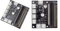
As has been highlighted in the most recent BBC micro:bit newsletter, we have just launched a new and improved version of our very popular Motor Driver Board for the BBC...
As has been highlighted in the most recent BBC micro:bit newsletter, we have just launched a new and improved version of our very popular Motor...
Way back when we first released our Motor Driver Board the microbit Block Editor only allowed digital write on the pins we used for controlling motors. This meant that motors had...
Way back when we first released our Motor Driver Board the microbit Block Editor only allowed digital write on the pins we used for controlling motors....
We’ve released several new robotics products recently that make use of servos and motors to provide movement. We recognised that creating code for the microbit to control these servos and...
We’ve released several new robotics products recently that make use of servos and motors to provide movement. We recognised that creating code for the microbit...
Thank you for your question, best thing to do is to have a look at the sample python code we have on our github repository. We have a guide / directory for those on the link below.
micropython-kitronik-bbc-microbit
The code for the robotics board is the closest we have to a guide on the motor driver as they work very similarly.
Best Regards
Cullen
Which is correct? :-)
I am building a robot and have the motors working, driven by 4 AA batteries. I now would like to use an ultrasonic sensor to avoid obstacles. This needs 5V - how do I get this supply?
Thanks
John
Thank you for your question, you wouldn't be able to draw the power directly from the board. You would need to power the sensor separately and twin the ground with one pin reading the data.
In theory it is yes you could link it to an input pin on the Pin break out for the motor driver board.
Best Regards
Cullen
Thank you for the question, in theory you could use this with an RC, though it would depend on the specifics of what you are trying to build e.g the voltage and current of the motors you want to run. The board operates the motors directly connected to it so it is not set up to be a hand held controller for motors but could receive radio commands from another micro:bit to control the motor outputs.
Thank you for your question, that should be possible. Simply attach a switch to the 3V and one pin 1 or 2 on the gold break out strip. You could then code it so that pin being high or low acts as an extra input for the code.
Best Regards
Cullen
I have now connected the microbit to the motor controller and I am able to get the motor controller to turn on a 6 V relay when I press the start button. What I now want to do is to get the 6 V relay to turn on in response to switches being turned on that are connected to pins 0, 1, and 2 of the microbit (or their equivalent since these portions of the board are no longer accessible; they are buried in the motor controller). I see the motor controller has a ground and pin markings for 0, 1, and 2, but when I connect a switch across ground and pin 1 and press it (with the code I wrote for my other games), it doesn't seem to work the same way. Do you know what is going on? (I realize my question is a little complicated!!).
By the way I am trying to get the motor controller to turn on the relay for a few seconds when a switch is triggered so that I can control a 12 V pump and make games that spray water but only for a few seconds (everything is working except my ability to get the relay to respond to the pin value jumping from 0 to 1 due to the switch being turned on).
Thanks for any help you can give. I do appreciate it!!
Thank you for your message, I have had a look for you and it is because pins 1 & 2 are the pins used to run the motor so if you swap to a different set of pins that should all work for you!
Best Regards
Cullen
I am in the process of developing step by step wiring diagrams for students using your break out motor board. Have you any CAD drawings for your motor driver board that could be used to show connections etc. Also I use Fritzing mainly for producing circuit diagrams in school and students respond well to it. Does Kitronik have any part blocks available for Fritzing or any plans to develop same. At present I can use a Microbit part in Fritzing but students become confused when using a breakout board.
Thanks in advance.
Thank you for your question I have been looking into this for you unfortunately we cannot supply the CAD files for a lot of our kits. Any we do have are already available on the product pages. We have had a look into fritzing as it is not something we currently use and while it might be something we look at for future it is not something we currently have.
best Regards
Cullen
Thank you for your question so the micro:bit sites updated guides for getting started are here below. I believe that is the link that was on the previous question.
https://support.microbit.org/support/solutions/folders/19000126498/page/1?url_locale=
By the Github code I assume you mean adding the extra packages such as for the motor driver board that are hosted on github?
You can add these extensions to your project by clicking on the advanced section on the right hand side of the screen. You should then see an extra set of options at the bottom of these is a plus sign with the word "Extensions" next to it. If you press this you should then be presented with various extra packages you can add to the code. If you cannot see the one you want you can always search for it in the search bar.
I hope this helps!
Cullen
16 Servo Driver Board allows up to 16 servo's to be driven by the micro:bit at any one time. The
All-in-one Robotics Board allows for up-to 4 motors or 2 stepper motors and up-to 8 servo's to be driven at any one time by the micro:bit.
Thank you for your question, it should work fine from this though you would likely need to do the coding manually rather than use one of our pre packaged block packs.
Best Regards
Cullen
Do you have anything I could use for 4 motors rather than two?
Also, we are in the process of releasing a board that can control 4 motors and 8 servo's. This should be coming in the next couple of weeks.
I would like to use the motor driver pins 0, 8, 12 and 16 to control up to 4 x 5V relays. Normally when controlling motors you need to add a "flyback diode" to protect electric components when the magnetic field inside the motor or relay collapses. Can you please indicate if there is inbuilt protection on the motor driver board v2 or if I should add "flyback diodes to each of my relay circuits. One terminal of the relay will be connected to pin 0,8,12 or 16 and the other terminal will be connected to the ground of the supply terminal to the motor drive board.
Thanks again - enjoying the versatility of the motor drive board.
Edmond Lascaris
I´m driving two servo with the board and when I use pin 8 and pin 16 everything seems ok.
Pin 8 is a 0-180 servo and pin 16 is Servo CR.
If I instead use pin 12 and pin 8, both for motor 1 there seems to be a problem.
Should I use different "motor"-pins or could I use both pins for Motor 1.
If I could use both pins for Motor 1 och both for Motor 2, then I thought I could use four servos, but that shouldn´t be possible?
It looks like this:
https://www.youtube.com/watch?v=R8-5NXMeBN4&index=6&list=PLmwZRQqL38s34xMUckBFNk0Cz8wpV_FNM
Thanks Nick
Hi Marcus, It is possible to control the motor speed by using the Analogue Write Pin block. Because the micro:bit is limited to 3 analogue out channels at any time the technique to do this is: Use the Analogue Write Pin to drive one pin of the motor, and use Digital Write Pin to set the other pin to zero To drive the motor in the other direction swap the pins which are analogue and digital write over.
Is there any chance to access P19 and P20 (I2C) if the LED matrix of the micro:bit is oriented towards the DRV8833?
Hi Marcus, Unfortunately it isn’t possible to access pins 19 and 20 while the BBC micro:bit is facing the terminal blocks on the motor driver, you can only access this when it faces outwards.
Hi Kal, We don’t have any resources designed to give a step by step on creating circuits with the motor driver board, however we do have a few resources that might be helpful. Anything BBC micro:bit related can be found here bbc-microbit-kitronik-university, and we do have a breakdown of what the different blocks do to help understand what each section would do, getting-started-microsoft-block-editor. We also have the code for the line following buggy kit, 5604 available here to download so it may be that you could create your own buggy with son and adjust the code to suit your design, https://www.microbit.co.uk/app/#list:installed-scripts:script:5c7ac527-2145-475e-0c20-2280d1412664:overview:id=lapexp
2. Do the breakout pads contain plated-thru holes to insert and solder a 21-position, 0.1 inch terminal strip? This seems implied by the mention of "PCB pin headers" in the description, but the photograph appears to show small (via sized) holes in the pads plugged by solder mask.
Hello Bill, The answer to your first question is yes the BBC micro:bit would still receive power from the motor driver board regardless of which way it is placed into the connector. With regards to your second question the holes on the board shouldn’t contain and solder mask and I believe that the ay the image has been taken it applies they are blocked. The holes doe go completely through the board and a suitable item to use on these pins would be 4133-straight-single-row-pcb-pin-headers-254mm-36-way.
Hi Paul, The 6V’s that we state would be the maximum that the board could handle, this would be due to limitations on other components such as the regulator, however I don’t have full details all the maximum voltage for all the components so there might be a few more.
Hi Brendan, The formula in the datasheet states that typically at 1.5A as an output current the output voltage (Vm) will be 0.3V less than the voltage input(Vcc). So if you put 6V’s into the motor driver board you would typically get 5.7V’s as an output on the motor terminals.
Ask a question about this product
Payment & Security
Your payment information is processed securely. We do not store credit card details nor have access to your credit card information.


