 This Kitronik University resource is part of the BBC micro:bit partnership and is an in depth tutorial into making an edge connector light level detector with the BBC micro:bit.
![]()
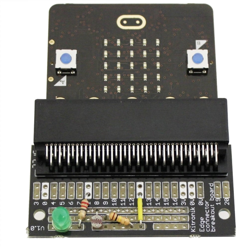
This is a simple tutorial demonstrating how to use a Kitronik edge connector breakout with the BBC microbit. The tutorial will cover measuring ambient light levels with an LDR and dimming an LED correspondingly. In this example we will use the prototyping space on the breakout board with an LDR, two resistors and an LED.
BBC microbit Edge Connector Light Level Detector:

Learn how to:
- Program your BBC micro:bit to read an external sensor.
- Control an LED based on light levels.
- Breakout the BBC microbit using a Kitronik Edge Connector
Level of difficulty:
- Beginner.
Parts List
In order to make your BBC micro:bit Edge Connector Light Level Detector you will need:
- 1 x BBC micro:bit.
- 1 x Edge connector breakout board.
- 1 x LED (most standard LEDs with a forward voltage no higher than 3V should work).
- 1 x miniature LDR (dark resistance 20M, light resistance 5K).
- 1 x 100K resistor.
- 1 x 220 Ohm resistor.
- 1 x Battery Cage.
- 2 x AAA Batteries..
- 1 x USB to Micro USB lead.
- 1 x Length of wire.
You will also require the following equipment:
- A computer with a USB port and internet access.
Step by Step Guide to making your “BBC micro:bit Light Level Detector”
Step 1

First this tutorial will cover the code for the dimmer; the later steps will cover the hardware side of things. Go to the BBC micro:bit website, click “Let’s Code” then open the MakeCode Editor by clicking the button. Let’s practice using the block system to build some code. The blocks are organised into categories and the categories are listed in a column down the left hand side of the screen.
Step 2

First we need to create a “forever” loop. This is the block that the rest of our code will sit inside. The “forever” loop runs all the blocks inside it starting from the top and working its way to the bottom. Once it gets to the bottom block it starts again at the top and this process will continue forever. Click on the “Basic” category to open it and then drag the “Forever” block into the workspace. (This is the big white area in the middle of the screen). The forever block is useful as it runs the program again from the beginning once all of the steps have been completed.
Step 3

This will require us to store and use data from a pin on the BBC micro:bit. To do this first we will create a variable, this is a location where we can store data in the BBC microbit’s memory. We will then pull data from the pin and store it in that variable. Click on Variables, then click the Make a Variable button. Choose a variable name, we chose “light level”. We will use this variable to store data from the LDR. The data stored will be a number between 0 and 1024 as this is how the BBC micro:bit sees analogue data. Drop this block into the forever block you just placed and you should find it snaps into position.
Step 4

Now that we have a variable ready to store temperature information we need to get the information from the sensor and put it into that variable. The way to do this is to perform an “analog read”. Attach an “analog read pin” block to the variable you just made. The “analog read pin” block is used to read data from a pin that you can select by clicking the drop-down menu to the right hand side of the block. These blocks, when combined, will read the value from the selected pin and set the variable you created to that value. In this tutorial, we will read from pin P2.
Step 5

Now we need to do something with the information gathered from the “analog read”. Grab an “analog write” block and clip it underneath the first block. Set the pin to P1. Replace the number block from the “analog write” block with our variable “Light Level”. The brighter the light that shines on the LDR the higher the output will be driven.
Step 6
Now would be a good time to put what we’ve just done to the test. First, however, we need to set up the hardware. Take your 100K resistor and solder one leg to the negative strip in the prototyping area (marked with “-“) on the edge connector breakout. Solder the other end onto the centre strip at the edge of the board. Next solder the LDR. Put one leg through the positive strip (marked “+”). The other leg should go into the centre strip at the edge of the board. Take a short piece of wire and connect the centre strip at the edge of the board to the pin labelled “2”. Next, take your current limit resistor and solder one end into the pin labelled “1”. The other end of the resistor should be soldered into the left hand strip at the edge of the board. Finally, take your LED and solder the long positive leg into the left hand strip at the edge of the board, and the short negative leg into the negative strip (marked with “-“).
Step 7
Now, let’s try that out! Press Download and after a few moments the code should appear as a download in your browser. If you plug your BBC microbit into a USB port it will show up as a storage device. Simply drag and drop the .hex file you just downloaded onto the BBC micro:bit. Once the file has been transferred, the light on the BBC micro:bit will stop blinking rapidly.
Further Tasks

If we wanted to invert the function of the light sensor board we have built so that the LED lights up when the LDR is covered, we can do this in the code. The analogue value read from pin P2 will be between 0 and 1024, so if we want to reverse the reading we can subtract it from 1024. So a reading of 0 will become 1024 and a reading of 1024 will become 0. Download a pdf version of this page here. ![]()