Motors provide a clean way to convert electrical energy (such as from batteries) into mechanical energy (or movement.) This document explains what a motor is, a little of the theory about how it works, and shows some of the different types of motors.  It illustrates how motors can be controlled, and what limitations there are in their use. This guide assumes a basic knowledge of electricity.
Electric Motors – A Brief Guide – A Little History:
Electric motors have been around for a long time, roughly 200 years. Whilst there is more than one type of motor the most common ones in use today, and the ones we are interested in in this document use the principles of electromagnetism to provide motion. Michael Faraday is credited with discovering the laws of electromagnetic induction in the early 1800s.
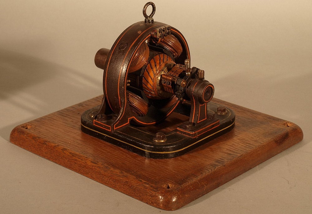
 Figure 1: A Victorian electric motor
How does a Motor Work?
Motors convert electrical energy into mechanical energy. A basic motor is made up of a magnet and a coil of wire. When current flows through a wire, it creates a magnetic field. Placing another magnet near to this field creates a force. The size of the force depends on three factors;
- The amount of current flowing in the wire
- The length of the wire
- The strength of the magnetic field
The force can be calculated by the following equation:
Force α (current) x (wire length) x (magnetic field)
Increasing any of these factors will increase the force and therefore increase the speed of the motor. The direction of the current, the magnetic field, and the resulting force are related. John Ambrose Fleming devised the Left hand rule to show the direction of force on a current carrying wire in a magnetic field.
 Figure 2: Illustrating Flemings Left Hand Rule
Fleming’s Left Hand Rule (figure 2) shows:
- Direction of the current flow in the wire (middle finger).
- Direction of the magnetic field (Index finger).
- Direction of the force created (thumb).
The direction of the force shows the direction that the motor coil will move, and hence the direction of rotation.
Brushed Motors:
In order to allow current to flow through a moving wire, a brush is used. This slides over the connection surface. In a brushed motor this rotating surface is called a commutator. In the following example, the commutator is split into two, to allow connection to each end of the single coil of wire. Typical motors have commutators with many segments. Each end of the coil is connected to a part of the commutator and will rotate with the motors shaft. As the commutator rotates, it connects with two contacts, known as brushes (a positive and a negative brush). Because the commutator is split this causes the current to continue to flow in the same direction as the motor turns, even though the ends of the coil have changed. Figure 3: Diagram showing parts of a motor
 Figure 4: Showing an ‘ideal’ motor[/caption] When a voltage is applied (via the commutator) current flows around the coil. A force is created from the magnetic field, and the coil moves away in accordance with Flemings Left Hand Rule.
 Figure 5: Showing an ‘ideal’ motor
As the coil rotates towards the opposite side the force would change direction, and the motor would not spin. To prevent this the commutator switches the current to flow in the opposite direction through the coil, which then continues to rotate.  Figure 6: Showing an ‘ideal’ motor
This process is done every half turn and keeps on repeating while there is a supply to the commutator. To change the direction the motor turns, simply change the polarity of supply to the commutator. Typical DC motors have multiple coils and commutator segments to ensure that they run smoothly, and can start easily.
Direction Control:
A commonly used method of switching the direction of current flow is called the H bridge (figure 7) It is known as this because its schematic representation is often drawn to look like a capital letter H.  Figure 7: Schematic of an H Bridge
It has 4 switches, often Field Effect Transistors (labelled 1, 2, 3 and 4), which can be controlled in pairs, one from the top and one from the bottom on opposite sides of the motor (1 and 4, or 2 and 3). Turning on both switches on the same side will short circuit the power supply to ground, which is not a good idea. Most motor driver circuits have inbuilt protection to prevent this from happening. A single H bridge can be used to control a brushed DC motor, both for direction, and with some additional work, speed. Figure 8 shows the current flow (red arrows) for forwards and reverse of a motor.  Figure 8: How current flows in an H Bridge
Speed control:
The speed a DC motor runs at is related to the power that is supplied to it. Most motor datasheets will specify a no-load speed at a certain voltage. Because of Ohms law (Volts =Amps x Resistance), this also implies a certain current, and therefore a certain power input (Power = Volts x Amps). The No Load speed is the speed that the motor will get to with only the inbuild friction slowing it down. Once a load is applied to the motor – such as turning a gearbox to drive a wheel – the motor will slow down unless the input power is increased. At the rated voltage and current, the motor will produce the rated torque and turn at the rated speed. If the output asked for is too great then the motor could stall. At that point, the maximum current will flow (usually referred to as the Stall current.) Figure 9 shows an extract from a datasheet for a small DC motor.
 Figure 9: Extract from a small motor datasheet
The power input can be controlled by varying the voltage (or current) available to the motor. This might be a simple as adding a variable resistor into the circuit, but it is more common to use a technique called pulse width modulation (PWM) to control the motor from a microprocessor. PWM controls the average voltage (and therefore current – they are related by Ohms law) over a period of time by switching the voltage on and off much faster. If the ‘On’ time is equal to the ‘Off’ time then the average is 50%. Figure 10 shows 3 waveforms. The top waveform has an average power of 50%, the second waveform and average power of 25%, and the bottom waveform an average power of 75%.
 Figure 10: Illustration of PWM waveforms
By controlling the power available to the motor we can control its speed.
Removing the Brushes:
Because the brushes and commutator are constantly sliding over each other eventually they will wear out. When this happens the motor will no longer run. It is possible to build an electric motor without brushes – these motors are called brushless motors. A brushless motor is conceptually inside out from a brushed motor – the coils of wire stay still, and the magnets are attached to the rotating shaft. There are 2 main sorts of brushless motors – Inrunners (Figure 11) – where the magnets are inside the coils, and Outrunners – where the magnets are on the outside of the coils. (Figure 12)
 |
 |
 |
Figure 13 shows a disassembled Outrunner. The magnets on the rotor can be clearly seen, as can the fixed coils of wire. As we have seen to allow the motor to turn there needs to be a method of changing the direction of current flow in the coil of wire. This is called ‘commutation’. The example shown in figure 4 et seq. illustrates a brushed motor. There are other ways to achieve commutation without using brushes. Stepper motors and ‘Brushless’ motors use an external controller to take the place of the rotating commutator on the motor shaft. This external controller is responsible for switching the direction of the current to keep the motor spinning. Brushless controllers are similar to sets of H bridges, but they switch direction more often in order to keep the motor spinning in the same direction! There are various methods of ensuring the switching happens at the correct time. These involve either a sensor on the motor, or using the motor itself as a sensor. The detail is not important for using a motor controller, as long as you pair a sensor controller with a sensored motor or a sensorless controller with a sensorless motor. The vast majority of hobby motors and controllers are sensorless.
Which motor do I have?
A brushed motor usually has 2 connection points. These connect to the brushes inside the motor. Figures 14, 15 and 16 show different brushed motors. If the motor has wires coming from it then these can be used to connect it up. Most brushed motors, however, have tags on the motor to connect wires to.
 |
 |
 |
Figures 17 to 19 show how to attach wires to the most common type of brushed motor tag. The wire is stripped and then fed through the hole. It is then bent back on itself, which provides mechanical security. To provide a good electrical connection the bare wire and tag are then soldered.
 |
 |
 |
When connected up if the motor turns the wrong way then simply swap the 2 wires over.
 |
 |
It will also need a dedicated brushless motor controller, which will have 3 connections for the motor, and 2 for the power supply. Figure 20 shows the connections from a brushless Inrunner, and Figure 21 shows a typical brushless motor controller. This controller is designed for use with a Radio Control (RC) system, so as well as the motor and battery connections it has a servo plug as well. When connected up if the motor turns the wrong way then swapping any 2 of the 3 wires will reverse the direction. A stepper motor will have more connections. Common steppers have 4,5,6 or 8 wires. These connect to the different coils inside the motor, and need connecting to the correct place on a dedicated stepper motor driver. Because stepper motors are a specialist type of brushless motor the details of stepper motors and how to use them are covered in another guide.
Using a motor with a microcontroller:
The 2 main methods of controlling a motor (either brushed or brushless) from a microcontroller are to control an H bridge or brushless controller directly or to use an RC servo interface (which then drives the H bridge). Microcontrollers can usually only output very small amounts of current from their pins, so attaching a motor directly to them will not work, and could damage the microcontroller. Using the H bridge allows the program to directly control what the motor does. Often H bridges are built into dedicated Integrated Circuits (IC) for this purpose, which may also contain some protection features to prevent damage to the motor, the IC and the power supply. When using a servo interface the motor controller may be designed for use in aircraft or cars. Controllers designed for use in Aircraft normally only run in a single direction, as most aeroplanes don’t fly well in reverse. Car / Boat controllers will run a motor both forwards and backwards. There may be additional features, such as braking and speed hold. The motor controller’s manual should explain these. Typically a single direction controller will use the full range of the servo (1-2mS) for speed, whereas the bi-directional controller will use half the range for forwards, and half for reverse, with stop in the middle.
Conclusions:
Electric motors are a clean method of providing controllable movement. There are many types so most requirements can be accommodated, and also the methods of controlling them are simple. The main limitation of motors is their requirement for a source of electricity which can then provide enough current and voltage to enable them to perform the work required. Brushless motors trade the simplicity of a brushed motor for the lack of wearing parts. They require more complex control circuits but can then provide more efficiency and long term reliability.
By
David Sanderson, MEng (hons) DIS, CEng MIMarEST Technical Director at Kitronik
Images used in this document sourced from:
Figure 1: a Victorian Electric Motor, photograph, viewed 21st Mar 2019, https://www.earlytech.com/earlytech/item?id=564 Figure
2: Diagram of Flemings Left Hand Rule by Kitronik. Figure 11: Diagram showing parts of a motor by Kitronik.
Figure 4: Showing an ‘ideal’ motor, diagram by Kitronik.
Figure 5: Showing an ‘ideal’ motor, diagram by Kitronik.
Figure 6: Showing an ‘ideal’ motor, diagram by Kitronik.
Figure 7: Schematic of an H Bridge, diagram by Kitronik.
Figure 8: How currents flow in an H Bridge, diagram by Kitronik.
Figure 9: Extract from motor datasheet, viewed 21st Mar 2019, https://www.e-jpc.com/pdf/dcmotors601-0241.pdf
Figure 10: Illustration of PWM waveforms, diagram by Kitronik.
Figure 11: A Small Inrunner Motor, photograph, viewed 21st Mar 2019, https://www.valuehobby.com/2838-3600kv-inrunner.html
Figure 12: A Pair of Outrunner Motors, photograph, viewed 21st Mar 2019, https://www.scorpionsystem.com/info/brushless_outrunner_motors
Figure 13: A Disassembled Outrunner Motor, photograph, viewed 21st Mar 2019, https://apollo.open-resource.org/mission:log:2012:07:17:howto-disassemble-a-brushless-motor
Figure 14: A Geared Brushed Motor, photograph by Kitronik.
Figure 15: A Brushed Motor with wires, photograph by Kitronik.
Figure 16: A Large Brushed Motor, photograph by Kitronik.
Figure 17: Push Wire through hole, photograph by Kitronik.
Figure 18: Bend wire to secure it, photograph by Kitronik.
Figure 19: Solder wire and tag, photograph by Kitronik.
Figure 20: Brushless Inrunner showing connection leads, photograph, viewed 21st Mar 2019, resources.ripmax.com/product_images/combi/m/m-dhkh105.jpg
figure 21: Brushless motor controller, photograph, viewed 21st Mar 2019, By Avsar Aras – Own work, CC BY-SA 3.0, https://commons.wikimedia.org/w/index.php?curid=19639998https://www.futabarc.com/servos/analog.html