Description
One you’ve mastered starting and finishing off stitches you’re ready for this tutorial which describes how to create a basic E-Textiles circuit using a standard through hole LED. This circuit is slightly harder to create than one with a PCB LED as you have to twist the legs on the LED. This can be fiddly to do and it can be easy to forget which is the negative and positive leg once they are twisted.
Learn how to:
- Add a standard through hole LED to an E-Textile circuit.
Parts list
In order to add a standard LED to an E-Textile circuit you will need:
- Standard white LED.
- Miniature Coin Cell Holder and CR1220 Coin Cell (you could use any other type of cell holder).
- Conductive Thread.
- Round nosed pliers.
You will also need the following equipment:
So, let’s see how it’s done…

Tips for creating the circuit
Note that there are 4 rings on the cell holder. Only one positive and one negative ring is needed to create the circuit in this tutorial. When putting this circuit into a product, the rings could be stitched down using ordinary sewing thread to keep the cell holder stable. The rings can also be used to add another LED to the other side of the circuit.
Creating the circuit
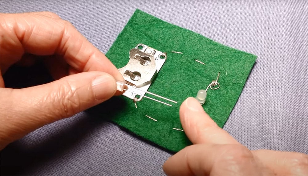
Use the round nosed pliers to create a small loop in the negative leg of the LED. The negative leg can be identified as it is the shorter of the two legs. Also there is a flat, cut off section on the bottom of the bulb directly above the negative leg. This can be a little hard to see so an easy way of remembering which leg is which is to always twist and stitch the negative legs in your circuit first and then do the positive side of the circuit. 
 Attach the loop that you have made in the negative leg to the fabric using 5 or 6 oversewing stitches. The stitches must be tight and clumped close together.
  Use running stitches to take your needle to the position where your cell holder will sit.
  Stitch the ring on the negative side of the cell holder onto the backing fabric using 5 or 6 oversewing stitches. Finish off the thread on the back of the fabric and trim the thread close to the stitches. The negative side of the circuit is now complete.
  To create the positive side of the circuit, twist the positive leg into a small loop with the round nosed pliers.
  Using a new piece of thread, stitch the loop on the positive leg onto the fabric using oversewing stitches.
  Use running stitches to take the needle and thread to the positive side of the cell holder and oversew the positive ring on the cell holder into position.
  The circuit is now complete. Push the cell into the cell holder with the positive side of the cell facing upwards.
  Also see our tutorial on adding a PCB LED to a basic E-textile circuit.