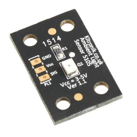
The last (for now) of our new breakout boards are now on the shelves. We complete the set with an Ambient Light Sensor Breakout Board, a Current Sensor Breakout Board (ACS711) and a Relay Control Breakout Board.
Ambient Light Sensor Board
This circuit uses an SFH 320-3/4-Z phototransistor and provides an analogue signal which gives a representation of the levels of light that are falling on the phototransistor on the board. This is achieved by creating a potential divider using a 2M2 resistor and the phototransistor. As the light level increases the resistance of the phototransistor decreases, which increases the voltage at the SIG pin. So by reading the voltage at the SIG pin you can determine how much light the phototransistor is being exposed to.
The board can easily be connected to a microcontroller and will operate at 3V or 5V.
Current Sensor Breakout Board (ACS711)
This circuit uses the ACS711 and can be used to measure currents ranging from -25A to 25A. The current you are measuring is routed into the pad labelled IP+ and back out of IP-. The board contains a range of hole sizes allowing for different gauge wires to be connected to the board. The IC then outputs the reading as an analogue signal between 0.3V and Vcc-0.3V to the OUT pin. When no current is drawn the output is at half the supply voltage, as the current draw increases the output moves further away from the centre point. If the device is operated from a 5V supply and is connected directly to a microcontroller analogue input (with a 10 bit resolution) then the resolution of the current reading will be 55mA.
The sensor works by utilising the Hall Effect so it must be kept away from strong magnets if it is to function correctly.
The board can easily be connected to a microcontroller and will operate at 3V or 5V.
Relay Control Breakout Board
This breakout board allows a low power logic level device running at 5V to operate a relay. The relay can switch up to 16A 250VAC or 16A 30VDC. This lets your low power microprocessor control big, power hungry devices!
To use the board you simply connect a constant 5V supply along with a signal connection. When the signal connection is taken high (over 2.1V) the relay and on board LED indicator turn on. At this point the relay which is normally open becomes closed circuit.


