Experiment 10 from the Inventors Kit for Raspberry Pi Pico, in which we controlling ZIP LEDs with code. Included in this resource are code downloads, a description of the experiment and also a video walk-through. This resource provides additional help and is not meant to replace the documentation that ships with the kit.
The Raspberry Pi Pico is a compact microcontroller based on the RP2040 processor – Raspberry Pi’s first in-house designed silicon. The RP2040 on the Pico uses 2 ARM processor cores, and also has 4 programmable IO controllers (PIO). These are like mini processors, and can help the Pico complete more complex tasks than it would otherwise be able to do. The Pico has 28 general purpose IO pins (GPIO), and 3 of these can also be used as Analogue inputs. The Pico can be programmed in several languages. The experiments in these resources are written in the Thonny Editor using MicroPython.
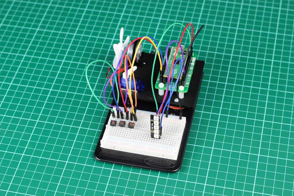
Pico Inventor’s Kit Exp’ 10 – Controlling ZIP LEDs
This experiment makes use of the ZIP Stick. ZIP LEDs are special LEDs which contain a processor and three separate LEDs (red, green and blue) in one package. They are individually addressable, which means each one in the chain can have unique colour settings, created by mixing the red, green and blue light together.
The communication protocol for the ZIP LEDs (the sequence of 0s and 1s which control the colour settings) requires more than simple PWM control, and this is where the Pico’s Programmable I/O (PIO) are very useful. A PIO is like a tiny processor which is able to run a small amount of code for a specific task. Importantly, the PIO operates independently of the main processor on the Pico, which means that timing critical processes, like controlling ZIP LEDs, are not affected by the main program running. The PIO cannot be programmed directly with MicroPython, but the code with the special instructions can be written inside the main MicroPython program.
- To learn how to use the Pico Programmable I/O (PIO) to create a state machine.
- To use the state machine to control ZIP LEDs (addressable RGB LEDs).
- To observe how different colours are made from mixing red, green and blue light.
Video Walk-through:

Exp 10 – The Code
All experiments are coded in MicroPython in Thonny. To open in Thonny, copy and past the code below directly into the Thonny editor.
'''
Kitronik Inventor's Kit Exp 10
Control a ZIP Stick (addressable RGB LEDs)
'''
import machine
import array
import time
from rp2 import PIO, StateMachine, asm_pio
numLEDs = 5 # Set the number of ZIP LEDs (5 on a ZIP Stick)
# Setup a PIO state machine to drive the ZIP LEDs
@asm_pio(sideset_init=PIO.OUT_LOW, out_shiftdir=PIO.SHIFT_LEFT, autopull=True, pull_thresh=24)
def ZIPLEDOutput():
    wrap_target()
    label("bitloop")
    out(x, 1)               .side(0)    [2]
    jmp(not_x, "do_zero")   .side(1)    [1]
    jmp("bitloop")          .side(1)    [4]
    label("do_zero")
    nop()                   .side(0)    [4]
    wrap()

ZIPStick = StateMachine(0, ZIPLEDOutput, freq=8000000, sideset_base=machine.Pin(16)) # Create the state machine on GP16
ZIPStick.active(1) # Start the state machine, ready to receive data
LEDs = array.array("I", [0 for _ in range(numLEDs)]) # Create array containing all the ZIP LEDs - "I" at start to indicate 32-bit number, then all 0s
buttonR = machine.Pin(13, machine.Pin.IN, machine.Pin.PULL_DOWN) # Setup an input button on GP13 with a human-readable name
buttonG = machine.Pin(14, machine.Pin.IN, machine.Pin.PULL_DOWN) # Setup an input button on GP14 with a human-readable name
buttonB = machine.Pin(15, machine.Pin.IN, machine.Pin.PULL_DOWN) # Setup an input button on GP15 with a human-readable name
# Initial states for the buttons are all False
buttonRState = False
buttonGState = False
buttonBState = False
# Interrupt handlers the RGB control buttons
def buttonR_IRQHandler(pin):
    global buttonRState
    buttonRState = True

def buttonG_IRQHandler(pin):
    global buttonGState
    buttonGState = True

def buttonB_IRQHandler(pin):
    global buttonBState
    buttonBState = True

buttonR.irq(trigger=machine.Pin.IRQ_FALLING, handler=buttonR_IRQHandler)
buttonG.irq(trigger=machine.Pin.IRQ_FALLING, handler=buttonG_IRQHandler)
buttonB.irq(trigger=machine.Pin.IRQ_FALLING, handler=buttonB_IRQHandler)
# Set the initial colours to have the ZIP LEDs all off, i.e. all colours at 0
r = 0
g = 0
b = 0
# Loop which continually checks for colour setting changes and sends these to the ZIP LEDs
while True:
    # Change the colour setting for red - cycles back to 0 if 255 is reached
    if (buttonRState):
        if (r >= 255):
            r = 0
        else:
            r += 5
        buttonRState = False
        time.sleep_ms(100)

    # Change the colour setting for green - cycles back to 0 if 255 is reached
    if (buttonGState):
        if (g >= 255):
            g = 0
        else:
            g += 5
        buttonGState = False
        time.sleep_ms(100)

    # Change the colour setting for blue - cycles back to 0 if 255 is reached
    if (buttonBState):
        if (b >= 255):
            b = 0
        else:
            b += 5
        buttonBState = False
        time.sleep_ms(100)

    # Send the RGB colour settings to the ZIP LEDs
    for i in range(numLEDs):
        LEDs[i] = (g<<16) + (r<<8) + b # Order is GRB
    ZIPStick.put(LEDs, 8) # RGB is only 24 bits, so get rid of unnecessary 8 bits
Inventors Kit Extra Resources:
Each of the ten experiments has been designed to ease you into coding and physical computing for the for the Raspberry Pi Pico. The experiments have been chosen to cover the key concepts of physical computing and they also increase in difficulty as you progress. This resource has been put together to provide additional information for this experiment and has not been designed to replace the booklet. The majority of the information you will need to perform and understand this experiment is contained in the booklet.
If you are new to coding and physical computing, even the least complex examples can be quite challenging. With this in mind, we created walk-through videos for each of the experiments. Our presenter talks you through the circuit in a way that backs up the information given in the booklet but in a style that some might find easier to absorb. As well as having a video walk-through, each page also contains the code. Although it is always good to tackle the code yourself, it can be handy for testing your circuit quickly. The code has been heavily commented as an extra learning resource. To get the most out of the experiment, once you've tested your circuit have a go at coding the experiment from scratch.
Follow the links in the table below:
| Exp No. | Experiment Name. |
|---|---|
| Digital Inputs & Outputs. | |
| Light Sensor & Analog Inputs. | |
| Dimming an LED using a potentiometer. | |
| Using a transistor to drive a motor. | |
| Control a servo with a potentiometer. | |
| Setting the tone with a piezo buzzer. | |
| Using a seven segment display. | |
| Exploring wind power. | |
| Capacitor charge circuit. | |
| Controlling ZIP LEDs. |