Experiment 3 from the Inventors Kit for Raspberry Pi Pico, in which we explore dimming an LED using a potentiometer. Included in this resource are code downloads, a description of the experiment and also a video walk-through. This resource provides additional help and is not meant to replace the documentation that ships with the kit.
The Raspberry Pi Pico is a compact microcontroller based on the RP2040 processor – Raspberry Pi’s first in-house designed silicon. The RP2040 on the Pico uses 2 ARM processor cores, and also has 4 programmable IO controllers (PIO). These are like mini processors, and can help the Pico complete more complex tasks than it would otherwise be able to do. The Pico has 28 general purpose IO pins (GPIO), and 3 of these can also be used as Analogue inputs. The Pico can be programmed in several languages. The experiments in these resources are written in the Thonny Editor using MicroPython.
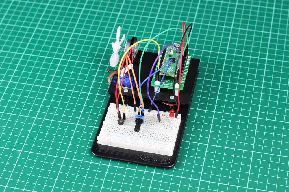
Pico Inventor’s Kit Exp’ 3 – Dimming an LED using a Potentiometer
This experiment uses a variable to track whether an LED should be turned on or off when a push switch is pressed. An interrupt routine is used to capture the button presses – this is a special function which can interrupt the current thing the processor is doing in response to an external input. Rather than constantly checking to see if an event has happened, interrupts are used to temporarily work on a different task with a higher priority. In this experiment, the main loop is constantly checking and adjusting the brightness of the LED based on the value of a potentiometer – it does this using Pulse Width Modulation (PWM) output. Later experiments go into more detail about how PWM signals work.
- To use a push switch to turn an external LED ‘on’.
- To use a potentiometer as a potential divider.
- To read the analog voltage from the potentiometer and use it to set the brightness of the external LED.
- To learn how to use software interrupts.
- To use a Boolean variable.
Video Walk-through:

Exp 3 – The Code
All experiments are coded in MicroPython in Thonny. To open in Thonny, copy and past the code below directly into the Thonny editor.
'''
Kitronik Inventor's Kit Exp 3
Switch on and off an LED via an interrupt, and change its brightness in relation to a variable resistor input.
A switch is connected to 3V3 Out and GP15.
This triggers an interrupt on the falling edge (i.e. when it has been pressed and released).
The interrupt toggles a variable which is used to turn on or off the PWM output on GP16.
The LED brightness is controlled by PWM on GP16. The variable resistor is read into Analogue input A0,
and its value is transferred to the PWM output.
'''
import machine
switchInput = machine.Pin(15, machine.Pin.IN, machine.Pin.PULL_DOWN) # Setup GP15 as the button input pin
LED = machine.PWM(machine.Pin(16)) # Setup GP16 as the LED pin with a PWM output
pot = machine.ADC(26) # Setup the analogue (A0) on GP26 with a human-readable name
buttonState = False # This variable tracks the button clicks.
# This is the interrupt routine that is attached to GP15 and triggers when the button is released.
def switch_IRQHandler(pin):
    global buttonState
    buttonState = not(buttonState)
# Attach the interrupt routine to the switch input
switchInput.irq(trigger=machine.Pin.IRQ_FALLING, handler=switch_IRQHandler)
while True:
    potValue = pot.read_u16() # This variable reads the voltage that the potentiometer is adjusted to
    # Now decide what to do.
    if (buttonState): # Then we want to turn on the LED
        LED.duty_u16(potValue) # Turn the LED on to the value of the potentiometer
    else:
        LED.duty_u16(0) # Turn the LED off
Inventors Kit Extra Resources:
Each of the ten experiments has been designed to ease you into coding and physical computing for the for the Raspberry Pi Pico. The experiments have been chosen to cover the key concepts of physical computing and they also increase in difficulty as you progress. This resource has been put together to provide additional information for this experiment and has not been designed to replace the booklet. The majority of the information you will need to perform and understand this experiment is contained in the booklet.
If you are new to coding and physical computing, even the least complex examples can be quite challenging. With this in mind, we created walk-through videos for each of the experiments. Our presenter talks you through the circuit in a way that backs up the information given in the booklet but in a style that some might find easier to absorb. As well as having a video walk-through, each page also contains the code. Although it is always good to tackle the code yourself, it can be handy for testing your circuit quickly. The code has been heavily commented as an extra learning resource. To get the most out of the experiment, once you’ve tested your circuit have a go at coding the experiment from scratch.
Follow the links in the table below:
| Exp No. | Experiment Name. |
|---|---|
| Digital Inputs & Outputs. | |
| Light Sensor & Analog Inputs. | |
| Dimming an LED using a potentiometer. | |
| Using a transistor to drive a motor. | |
| Control a servo with a potentiometer. | |
| Setting the tone with a piezo buzzer. | |
| Using a seven segment display. | |
| Exploring wind power. | |
| Capacitor charge circuit. | |
| Controlling ZIP LEDs. |