
This resource assumes that the reader has completed the Kitronik Discovery Kit for Raspberry Pi Pico, and has Thonny set up on a computer to program the Pico. This is the first of several extension experiments for the Discovery kit that will only be available online.
The aims of this experiment are;
-
- To understand the conversion from Voltage to ADC.
- To show that there is an onboard temperature sensor, and how to read it.
You Will need:
-
- All of the parts required or this experiment can be found within the Kitronik Discovery Kit for Raspberry Pi Pico, they are;
- 2 x Red LEDs.
- 1 Green LED.
- 2 Yellow LEDs.
- 5 x resistors.
- 6 x M-M Jumper Wires.
- All of the parts required or this experiment can be found within the Kitronik Discovery Kit for Raspberry Pi Pico, they are;
Raspberry Pi Pico Thermometer:
The Pico doesn’t have many onboard sensors, unlike the BBC micro:bit. It does however have an on-die temperature sensor.
We can use this to make a thermometer that displays the temperature via the LEDs included in the Discovery Kit.
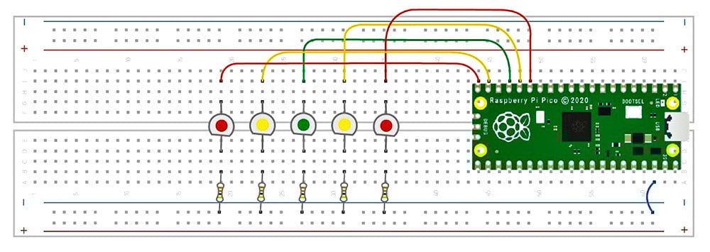
Build the following circuit on the discovery kit bread board:

Create the following code;
You can copy/paste the code below or download the file here.
import machine
import utime
tempSensor = machine.ADC(machine.ADC.CORE_TEMP)
ADC_count_to_volts = 3.3/(65535)
LED_Cold = machine.Pin(15,machine.Pin.OUT)
LED_Chilly = machine.Pin(14,machine.Pin.OUT)
LED_Nice = machine.Pin(13,machine.Pin.OUT)
LED_Warm = machine.Pin(12,machine.Pin.OUT)
LED_Hot = machine.Pin(11,machine.Pin.OUT)
LED_Onboard = machine.Pin(25,machine.Pin.OUT)
#at the start of each sensing cycle we turn off all the LEDs, so make a function for it.
def LED_AllOff():

    LED_Cold.value(0)
    LED_Chilly.value(0)
    LED_Nice.value(0)
    LED_Warm.value(0)
    LED_Hot.value(0)
#indicate we are running by turning on all the LEDs in a one at on manner
LED_Onboard.value(1)
LED_Cold.value(1)
utime.sleep_ms(500)
LED_Chilly.value(1)
utime.sleep_ms(500)
LED_Nice.value(1)
utime.sleep_ms(500)
LED_Warm.value(1)
utime.sleep_ms(500)
LED_Hot.value(1)
utime.sleep_ms(500)
LED_Onboard.value(0)
while True:
    #first read the temperature
    temperature = 27-((tempSensor.read_u16()*ADC_count_to_volts)-0.706)/0.001721
    #print the temp value to the console so we can see it.
    print("Temp: ",temperature)
    #now decide what to light up.
    #first turn off the last indication:
    LED_AllOff()
    if(temperature 17 and temperature19 and temperature21 and temperature<=24):
        LED_Warm.value(1)
    else:#it must be hot!
        LED_Hot.value(1)
#we can have a sleep - there is no need to check the temp as fast as possible.
#This will also help to prevent too much bias because the chip is running 'flat out'
    utime.sleep_ms(1000)
What’s going on?
What the code does is fairly straightforward. We read a value from the Analogue to Digital Converter (ADC), and then do some maths on it to convert it to a temperature figure. Then the code turns off all the LEDs and depending on the just calculated temperature it turns on one.
Because the temperature sensor is part of the RP2040 chip it is influenced by the amount of processing that the processor is doing. Because of this it does not provide a true reading of the ambient temperature. As an example, my test Pico reported 2 degrees lower than a thermometer in the same room.
The temperature sensor is an example of an analogue sensor. The sensor is internally connected to one of the ADC (Analogue to Digital Converter) channels. To get the value from the sensor we read that channel, which returns us a number.
The number the sensor outputs is not in centigrade. We can convert it to Degrees C (approximately)by using the following equation (from the RP2040 Datasheet) :
Temperature ~= 27 – (ADC_voltage – 0.706)/0.001721
When the sensor is at 27 degrees it outputs ~0.706V.
As the temperature varies from this the voltage changes by -0.001721 Volts for each degree hotter – That is the voltage goes down as the temperature goes up.
To access the sensor value we read the ADC channel it is connected to. The ADC reads voltages from 0 to 3.3V and returns a value of 0 to 65535. This means an ADC value of 19860 is approximately equivalent to 1V.
Because the Temperature equation is in volts, but we have a number in ADC counts we need to do some additional conversion. This is simple to define – we divide the ADC voltage range by the Count range – to give a voltage per count.
This is 3.3/65535, and is a constant, so we can do this calculation once and store it to be used in the equation.
The temperature equation then becomes:
temperature = 27-(tempSensor.read_u16()*ADC_count_to_volts)-0.706)/0.001721
where ADC_count_to_volts = 3.3/65535
The Pico ADC has 4 channels which are shared (multiplexed). To read the ADC we select a channel. The first 3 channels are brought out to the ADC pins, the temperature sensor is on channel 4.
This is abstracted to machine.ADC.CORE_TEMP which is used to give is a more obvious name for what is being read.
Abstraction also allows the higher level code to be unconcerned about the detail of the hardware it is running on – for instance a micropython version running on an ESP32 processor will still work using machine.ADC.CORE_TEMP.
To indicate the temperature we use 5 LEDs, with a centeral Green ‘Comfort’ temperature of 20 degrees, with yellow being slightly hotter or colder, and red being to 4 degrees hotter or colder.
-
- Red 24 degrees or hotter
- Yellow 21 degrees – 24 degrees
- Green 19 degrees – 21 degrees
- Low yellow 17 degrees – 19 degrees
- Low red colder than 17 degrees
Whilst fairly basic this code is an example of a real world sensor system, and provides a basis for expanding into data logging and multi-threaded operation in the coming tutorials.
Discovery Kit Extension Experiments:
The table below contains links to extension experiments for the Pico Discovery Kit. They have been listed in the order that they should be completed, and they should only be tackled once you have completed the 7 experiments supplied with the kit. Each extension experiment is thoroughly explained and code examples are provided. Although they cover quite challenging concepts, the information is provided in such a way as to walk you through the solution.
| Exp No#. | Experiment Name/Link. |
|---|---|
| 1 | Pico Thermometer. |
| 2 | Storing Data on the Pico. |
| 3 | Live Data Logging on the Pico. |
If you enjoyed this guide, make sure you don’t miss out on any other new free learning resources by signing up for our newsletter here