Radio Control (RC) Servos are a simple way to provide electronically controlled movement for many projects. Figure 1, for instance, shows a small RC servo controlled robot arm. In this document, the word ‘servo’ refers to a servo designed to be used with a radio control system, typically terminated in a 3 pin plug (figure 2). It does not refer to the more general, wide-ranging, description of a servo motor – that is a motor which has feedback control.  I am not aware of any actual ‘standard’ in the ISO (International Standards Organisation) sense that governs radio control servos. That said the many different manufacturers have mostly converged, such that most general purpose servos will perform as expected with most controllers.
Servos – A Brief Guide:
This document does not consider the advanced features that latest range of ‘digital’ servos may have (such as faster frame rates, programmable end stops etc). It treats things such as brushless motors, 7.4V lipo compatibility and similar as not important to the fundamental understanding it hopes to convey.
A little history:
Radio Control for hobby use has been around for a long time. Figure 3 shows a club meeting of The Johnson Space Center Radio Control Club around 1967, showing some very old RC equipment. Figure 3 The Johnson Space Center RC club
Multi-channel Radio Control systems existed in the 1960s and were relatively common in the early 1980s (when I started modelling as a hobby). This document is not especially concerned with the mechanics of how the control signal gets from the radio transmitters ‘stick’ to the radio receiver that would typically be controlling the servos – the radio part of RC. It is only concerned with how the receiver controls the servos, and how that can also be used in programmable systems.
Todays Servos:
The servos we buy today are based on a system that was devised by Doug Spreng and Don Mathes in the 1960s. They developed a servo mechanism that would respond to a changing pulse width. That pulse was 1-2mS in width and repeated over a ‘frame rate’ of 50Hz. To allow multiple channel control the system simply sends each servo in turn, followed by a ‘sync’ period of no pulses of at least 2 channels (4mS). This allows the receiver to ‘know’ when the first servo is, and hence to control the correct channels. Figure 4 illustrates 3 different pulse trains, with 4 servos in each at 1, 1.5 and 2mS pulse widths.
 Figure 4 Servo Pulse Trains
The Servo itself also generates a set of pulses and uses the width of the received pulse as a reference to adjust its internal timer. It does this by using the error (defined as the difference between the 2 pulses) to drive a motor, which then turns a set of gears. As it does so a potentiometer is also moved by the gear train, altering the internal timer. When the pulse trains match (within a deadband) the servo stops moving. The Servo output horn is fixed to the end of this gear train. An update rate of 50Hz is fast enough for most purposes, but if driving servos from a microcontroller they are usually quite forgiving of faster (and slower update rates.) If you do not send any control pulses then the servo will hold its last position, or give up holding position altogether. This is another none specified feature that varies from manufacturer to manufacturer.
Servo Ranges:
Typically the 1-2mS pulse used with a servo will create a movement range of between 60 and 90 degrees of the output shaft. +- 45 degrees is plenty for the control of a model aeroplane surface, the original design intention. (figure 5).
 Figure 5 Servo Horn (Red) at +- 45 degrees
A lot of servos are available, especially for robotics advertising different movement ranges: 90 degrees, 180 degree and continuous rotation being typical examples. Whilst it is possible to provide 180 degrees of rotation from the normal 1-2mS pulse this requires changing the gearing of the servo. A lot of the cheaper servos advertised as 180 degrees actually require a longer pulse to provide full travel. Remember that 90 degrees is typically a variation of 1mS, so for a generic 180-degree servo, the pulse must vary by 2mS. Often this requires sending a pulse of 0.5 to 2.5mS. Figure 6 shows how pulse width and servo horn movement match.
 Figure 6 Servo position related to pulse-width
This can be an issue for use with radio control systems, where there may not be a travel adjust option to stretch the pulses. More advanced radio systems are able to generate longer / shorter pulses to deal with this. If the servo is being used in a programmable system, for instance with an Arduino or micro:bit controlling it, then this is less of an issue. The software in these systems will allow control over both the pulse range and repetition frequency. Both of these systems (and many other hobbyist microcontrollers) can generate longer pulses. The Arduino’s popular servo library, for instance, uses 0.544mS to 2.4mS as it limits, and the BBC micro:bit generates pulses from 0.5 to 2.5mS
360 or Continuous rotation servos:
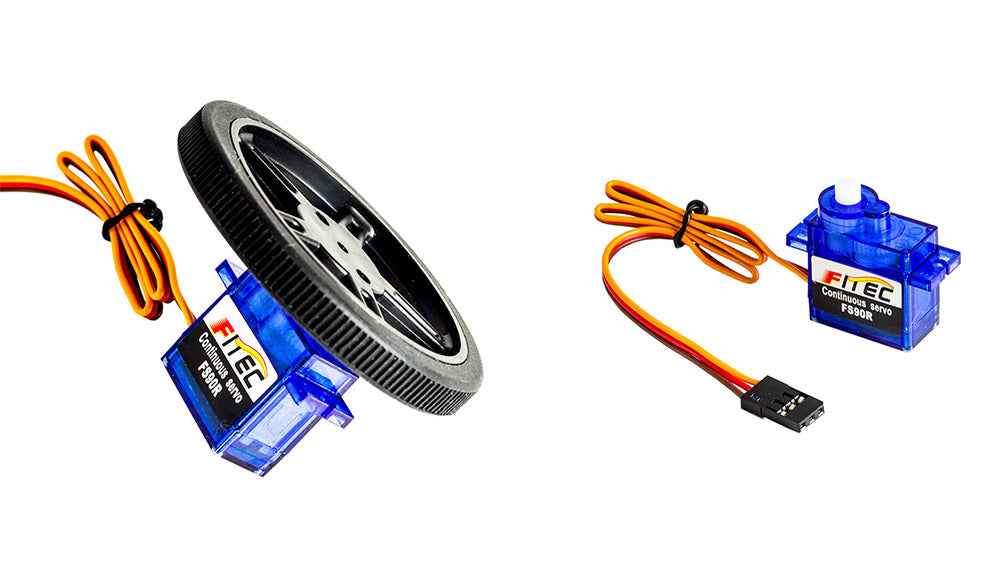
 Figure 7 A Continuous rotation servo and wheel
Whilst continuous rotation servos look like and are controlled like servos, (figure 7) they are actually not a servo system at all. The general description of a servo motor is a system with a motor and some positional feedback on the output of that motor. In a 360 degree servo, the feedback potentiometer is replaced with either a small trimmer potentiometer, which is not connected to the output shaft or a fixed potential divider, made from fixed value resistors. In a servo, the speed with which the output shaft moves to the commanded position is proportional to the error in position. With a 360 servo, the feedback is fixed at the neutral (~1.5mS pulse width) position. This then allows the command of a position to be effectively translated to a command of speed. Because the feedback is mechanically disconnected the error does not change, and the motor continues to turn. If the error is small (such as a commanded position of 100 degrees ~ 1.6mS) then the motor turns relatively slowly. If it is large, such as a commanded position of 180 degrees (2.5mS) then the motor turns fast. (figure 8)
 Figure 8 Commanded position vs speed of movement
Error and speed of movement:
Without getting into detail about control and system bandwidths it is simplest to say that the speed a servo moves is proportional to the error between the commanded position and the measure position. This is true for servos up to an error of about 20% of the travel. After that point, the servo is already moving as fast as it can and increasing the error won’t generally give any faster response. Going back to the origin of the system a 20% error in where a model aeroplane control surface is supposed to be is already very large. For servos, there are not normally any noticeable effects of this limitation. For 360 degree servos however it can mean that precise speed control is difficult – the speed range is compressed into a commanded position of around +-36 degrees. Add to this that cheaper servos exhibit ‘stiction’ where they don’t start smoothly, slight variations in the neutral position due to voltage fluctuations, and the effect is that to go at a precise speed needs very careful control of the timing of the pulse – a variation of around 400 microseconds (0.0004 seconds) is the full range of the speed control. If smooth, precise speed control of motors is required, but using a servo interface, then an RC motor speed controller is probably a better solution.
Power and signal limits:
The IC that was the de facto standard for servo controls was the Signetics NE554. This chip has a supply voltage of 3.2 – 6V, handily covered by 4x batteries – (around 4.8 to 6V). What many people don’t realise is that the input for the control signal is independent of the supply voltage, and it has a much lower threshold (of typically 1.5V). In radio control, the servos are usually operated at the same voltage as the receiver, and that is typically around 5V. When interfacing servos to modern microcontrollers the servo performance may be limited by the supply voltage required to run the controller – which can be around 3V. Fortunately, you can supply the servo with 5V (via its +V and GND pins) and it will still respond to control signals from a 3V microcontroller. Servos often specify a speed of response – typically so many seconds to move 60 degrees (see figure 9 for an extract of a typical spec sheet). 360-degree servos rarely specify a speed.
 Figure 9 Extract from typical Futaba servo spec sheet
The speed of response is mostly a factor of the gearing, which is fixed by the manufacturer, and the voltage. Often the ratings are given at 6V and 4.8V. Running servos on a lower voltage will slow them down. This doesn’t usually matter for most robotics projects, but can be important for applications such as radio control helicopters.
Conclusions:
RC servos are a simple way to add movement to many projects, and most of the detail in this document is not required to use them. It is hoped the background provided, however, may in future, make a difficult application simpler.
By
David Sanderson, MEng (hons) DIS, CEng MIMarEST Technical Director at Kitronik
Images used in this document sourced from:
Figure 1: a MeArm, photograph by Kitronik. Figure 2: Servo, photograph by Kitronik. Figure 3: The Johnson Space Center Radio Control Club, photograph, viewed 28th Feb 2019, https://www.jscrcc.com/images/history/picture_2.jpg Figure 4: Servo pulse trains, diagram by Kitronik. Figure 5: Servo horn positions, diagram by Kitronik. Figure 6: Servo positions related to pulse widths, diagram by Kitronik, Figure 7: A 360 degree servo and wheel, photograph by Kitronik. Figure 8: Commanded position vs speed of movement, diagram by Kitronik Figure 9: Extract from typical Futaba servo spec sheet, screenshot of webpage, viewed 27th Feb 2019, https://www.futabarc.com/servos/analog.html