We’ve recently added a continuous rotation servos to our range of stocked products. We thought it would be useful to do a quick tutorial on how to control one using a BBC microbit.

For this tutorial we used a Mini 360 Degree Servo, an Edge Connector Breakout Board for the BBC micro:bit and a microbit. It’s super simple to do and requires very few parts. We previously did a very similar tutorial for a 180 degree mini servo which you can read here.
Note:
Problem: Although we have used the BBC micro:bit as a power source for the servo, in this and other projects, this isn’t the ideal method. This has to do with the maximum amount of current that the BBC micro:bit can handle, using the BBC micro:bit to supply power to a servo has you very close to this limit. Powering the servo via the micro:bit may also illicit some code not functioning properly. Solution: Using a battery pack to provide power directly to the servo and only using the BBC micro:bit to supply the control signal to the servo is the best way to protect your BBC micro:bit from harm and to ensure that you are getting the full amount of torque etc from the servo.
Level Of Difficulty:
- Easy.
Parts List:
- 1 x BBC micro:bit.
- 3 x M/F Jumper Wires.
- Either 1 x Prototyping System for the BBC micro:bit.
- 1 x Mini 360 degree servo.
You Will Also Need:
- An Internet browser.
- A USB cable to connect the BBC micro:bit to the computer.
Controlling A 360 Degree Servo With A BBC micro:bit Process:
- 1 – Connect the Servo to the Breakout board.
- 2 – Write / download the code.
- 3 – Put the code onto the BBC micro:bit and test.
- 4 – Troubleshoot any issues.
Step 1 Connecting The BBC micro:bit To The Servo:

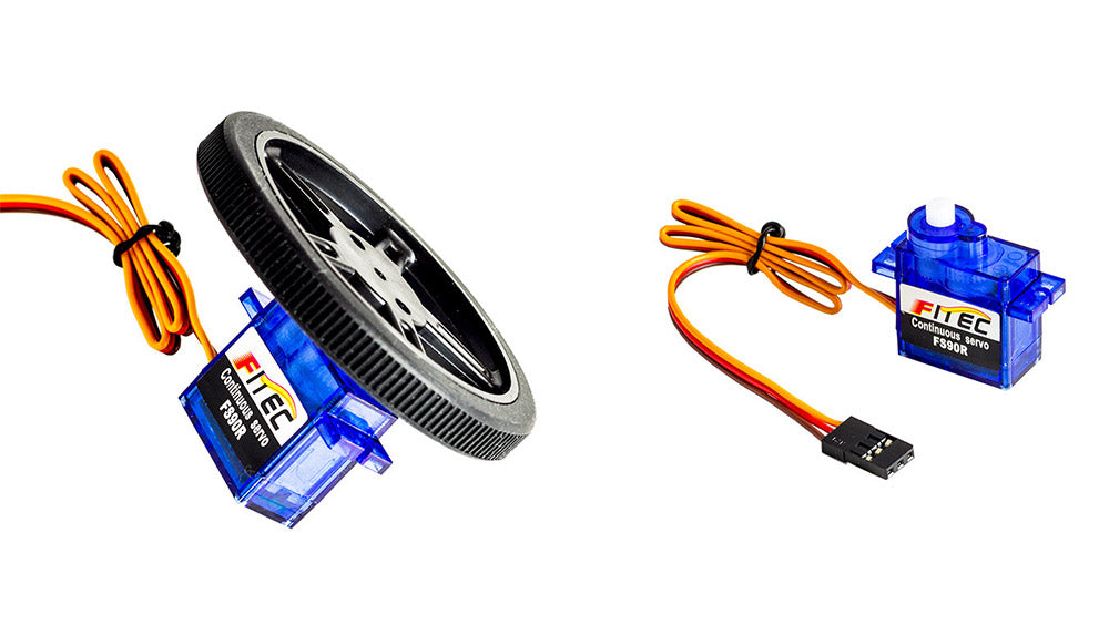
The servo has a three wire connector. The brown wire is ground, the red wire is positive and the orange wire is the signal wire, see picture above. The BBC micro:bit will send instructions to the servo from the P0 pin via the servo’s signal wire. Push the BBC micro:bit into the Breakout Board. Use the 3 x M/F Jumper wires to connect the Servo to the Breakout Board, the table below shows how the connections are made.
| BBC micro:bit Edge Connector Breakout Board | 360 Degree Mini Servo |
|---|---|
| 3V Pin. | Red Wire. |
| GND. | Brown Wire. |
| P0 Pin. | Orange Wire. |
Note: This experiment can also be done without the Edge Connector Breakout board. In order to do this you will need 3 x Crocodile Leads and you will need to cut off the Servo’s connector and strip the three wires. The connections in the above table remain the same if using this method, though you will be connecting the Crocodile Leads directly to the BBC micro:bit.
The Difference Between A 180 Deg’ Servo & A Continuous Rotation Servo:

Cosmetically the mini 180 degree servo and the 360 degree servo look the same, both are the same in size as the Tower Pro SG90 and are often used as a lower cost alternative. Its operation is very different to that of a standard servo. Instead of going to a specified angle, this servo will be static at a 1.5 ms pulse (a trimmer is included to tweak this), a longer pulse (duty cycle) gives forward rotation and a shorter pulse (duty cycle) gives backwards rotation. The pulse frequency remains at 50Hz regardless of the length of the duty cycle. If you are using the block editor for the BBC micro:bit to write code to control the servo then this is taken care of by the code behind the blocks but if you choose to write your code in something like ‘C’ then you would need to specify a pulse frequency of 50Hz in your code.
Step 2 Write The Code:
Now we know that the 180 degree servos and 360 degree servos are very different in operation, we’ll produce some code using the same blocks that we would use to write code for a 180 degree servo to further highlight the difference. We used the Microsoft MakeCode (Beta) editor to produce our code as it also includes a servo simulator that appears automatically when you insert servo blocks into your code.
As you can see from the embedded editor above, the code is very simple. The code basically delivers three things:
- The servo rotates in one direction at full speed for three seconds.
- It will then rotate in the opposite direction at full speed for three seconds.
- Then the servo stops rotating for three seconds.
The above code on a 180-degree servo would move the servo arm to the specified position and hold it there for three seconds before moving the arm to the next specified position. When using the 360-degree servo, the value instead denotes direction and speed and in the code above, we’ve shown the absolutes in both directions and the value at which the servo is stationary. Experiment with different servo write values to see what level of control you can exert. The show number block is just to give an indication on the BBC micro:bit of a change in step in the code. This cycle will continue until you either press the reset button on the BBC microbit or disconnect it from a power source.
You can download the code directly from the link below:
The linked Hex File has been zipped and will need to be unzipped before use. Download the code here. You can import the HEX file into the MakeCode editor if you wish to modify our code without having to recreate it by following the screenshot of the code.
Step 3 Download The Hex File To The BBC micro:bit And Test:
Once you have downloaded the code from one of the links above unzip the file, connect your BBC micro:bit to your computer via USB. Navigate to the file you unzipped in your downloads folder and drag it straight onto the BBC micro:bit in File Explorer (Windows). Once the .hex file is on the BBC micro:bit, press button A and the servo should move and continue to loop through the code until you press the reset button on the BBC micro:bit. The keen-eyed amongst you will have noticed from the code screenshot that we had a micro:bit uploader program running. This program automatically puts the HEX file onto your micro:bit when you hit the download button in the blocks editor. It will only work if this program is running at the time you download the HEX file. It is a great time saver. You can download it from here.
Step 4 Troubleshooting:
- Check that you have connected the servo to the breakout board correctly, refer to the table in Step 1 for guidance.
- Ensure that the M/F jumper wires are pushed into the servo connector securely.
More Information:
For more information, visit the product page. Or alternatively you can add one directly to your shopping cart below: