This resource has been designed to show how you can use our uncased memory stick modules as the basis for a 3D printing project. A memory stick is a great place to start when learning how to use 3D Printers and CAD software. This is because they are small in size, meaning they are quick to print (when compared to larger designs), but can still offer a wide range of learning and design experiences.
Below is a selection of pictures showing some of the example designs that we have created.


The main thing that we have focused on is demonstrating a variety of ways of fixing cases together (slide, clips etc…). We have kept the designs simple so that you can easily see how they work, though they could easily be altered to create bespoke shapes. All of the techniques described could be applied to cases for alternative types of products.
Design Resource Files
Below are the design files that we have used to create all of the designs shown in this resource. The include the CAD model of the memory stick itself and also the case design. Please feel free to download these files for use in your own designs and lessons (if you are a teacher).
- STL files (All cases)
- STEP files (All cases)
- USB memory stick Autodesk Inventor files
- USB memory stick STEP file

All of the designs have been test printed on a Robox 3D Printer. Depending on the type of 3D printer or filament you decide to use you may need to alter the designs slightly to get the best result from your particular setup. If a design requires a certain type of printer filament we have mentioned this below.
Working In CAD
All the images and graphics shown on the page were created using Autodesk Inventor and Autodesk 3DS Max. This is available free to education establishments and students. Lots of other CAD packages are also available.
One of the other advantages of working in CAD is that you can create fantastic looking animations like the one shown below.

Case Styles:
Slide together

The key features of the slide together design are:
- A rail for one part to slide onto the next. You can see this in the left hand image below.
- A small bobble on the inside which pops into place and holds the case together. The recess into which this bobble engages can be seen at the top centre of the right hand image below.

Key things that we took into consideration when modelling this case were:
- Keeping the angles of the rails at 45 degrees. This allows them to print well (as no severe overhangs) while still providing a good ‘keying’ between the two parts.
- Leaving enough space between the rails to make them not too loose and not too tight (around 0.3mm gap).
We find this case works best when using ABS filament, as PLA gives a slightly looser fit on our printer setup. This is due to the slightly different shrinkage rates between the two materials. You may wish to adjust the design to give the best results on whatever printer / filament setup you are using.
Screw together

The screw together case is a strong, simple fixing method using self tapping screws to pull the two parts together. One part has a countersunk hole for the screw to fit through, the other has a hole smaller than the screw. As the screw is pushed into the plastic it will create it’s own screw threads.

Key things that we took into consideration when modelling this case were:
- Not placing the holes too close to the inside or outside edges. This is to make sure the area the screws tighten into have enough mechanical strength not to break when they are tightened (see the ‘bulged’ area in the design above).
- Also make sure to know what screws will be used before modelling any holes to be sure they will not be too tight and break the plastic. If the the hole is too small in relation to the screw then this could easily occur.
- As this case has a chamfer (the 45 degree angle between the base and sides) it may be prone to warping. This is where the filament can ‘curl’ slightly on cooling. By modelling ‘ears’ (right image above) into the design the print will have better adhesion to the bed which can help prevent this. These ‘ears’ will need to be removed (cut away) one the print is complete.
Snap together

The snap together case uses a clip which flexes when pushed over the second part until it snaps into place. The clips can be printed quite small which keeps the case looking clean and seamless.

Key things that we took into consideration when modelling this case were:
- Making sure the clips wall thickness is large enough to prevent print layers from snapping or peeling off.
- Using a 45 degree chamfer on the clips will also prevent them from breaking.
This case will work best when using ABS filament. This is because ABS is mechanically stronger and more flexible than PLA (click here for more information).
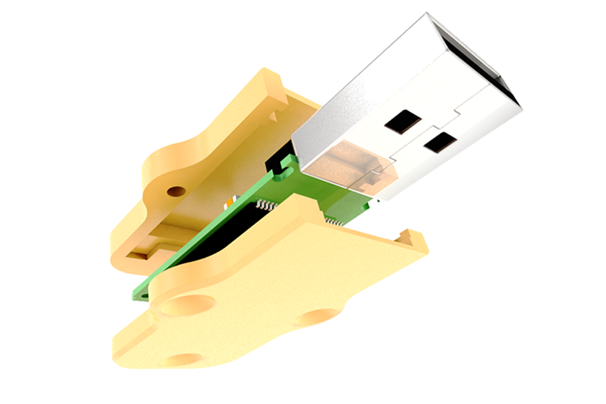
Push together

The push together case slots and holds together with friction. This means there are no difficult to model clips or fastenings.

Key things that we took into consideration when modelling this case were:
- To ensure the the two parts of the case are reliably connected we have used have slots (friction connection points) at the sides and back of the design.
- It is also important to make the slots slightly bigger than the studs to account for any inaccuracies during printing. We normally start with around a 0.2mm increase and then fine tube to get the desired results.
Other Useful Tutorials
- How to customize a USB case design using Autodesk Inventor. In this example we will show you how to write your name on one of the cases. Click here to download our guide.
