What is a Potential Divider / Voltage Divider?
A potential divider could be thought of as a voltage divider and it is often referred to as such. A Volt is just a unit of ‘potential difference’ in electric charge between two objects. 
How does it work?
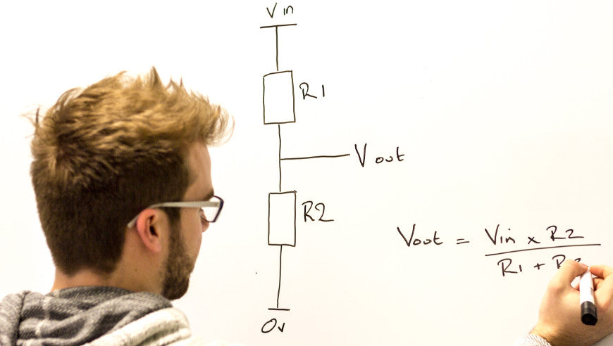
A potential divider is a simple circuit which takes advantage of the way voltages drop across resistors in series. It is a very useful and common circuit and is widely used in our range of electronic kits. The idea is that by using two resistors in series it is possible to divide a voltage and create a different voltage between them. In the example below two identical resistors are in series with a power supply. The total voltage across the circuit is ‘Vin’ however this total voltage is split between our two resistors meaning ‘Vout’ is at a different voltage. The amount by which the voltage drops over across each resistor depends on the relative values of each resistor and the total resistance.
<
p style=”text-align: center”>
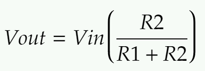
The formula for working out the voltage drop across two resistors in series is:
<
p style=”text-align: center”>
One of the most useful ways to use this circuit is to replace R2 with a variable resistor. If R2 can be controlled by turning a dial then Vout can also be controlled. This is used for tuning or volume control in many circuits such as in our FM Radio Kit V2.0 or 3W Stereo Amplifier Kit. Another common use of the potential divider is to replace R2 with a sensor such as an LDR. Then as the resistance of the sensor changes, Vout changes as well. This change can then be used to trigger a transistor or can be fed into the input of a microcontroller. For more details of how to do this, please visit our How an LDR Works resource.
Example:
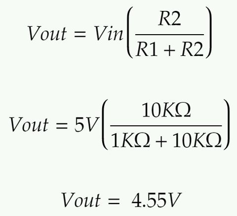
This is a worked example of using the formula above to calculate the missing Vout value for a circuit. Look at the circuit below and take note of the values that are known. Vin is 5V, R1 is 1KΩ and R2 is 10KΩ
<
p style=”text-align: center”>
Next, substitute the known values into the formula:
<
p style=”text-align: center”>
Example Questions:
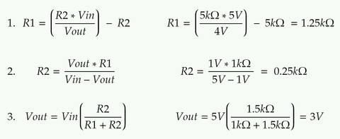
Now try finding the missing values in these three examples. Question 1:
<
p style=”text-align: center”>
Question 2:
<
p style=”text-align: center”>
Question 3:
<
Answers:
<
p style=”text-align: center”>
You can download a PDF version of this resource here.
The Project Shopping List below is a list of project kits that contain a voltage divider as a part of the design. Any of these kits would serve as a practical example for the classroom.


