If you are new to the Pico, and Python development, check out Raspberry Pi’s guide to get you started
Kitronik have also written a First Steps Tutorial to get you started using the Pico with the Thonny Editor.
Getting the Smart Air Quality Code
Kitronik have written a module to use with the Pico Smart Air Quality Board which is available, along with sample programs, in the Kitronik GitHub.
If the words “Clone the repo” mean nothing then check out our guide to git
If you are new to using modules with the Pico, there is a helpful guide providing practical examples and explanations on how to do so.
Clone or download the repository and then copy / save the PicoAirQuality.py file to your Pico.
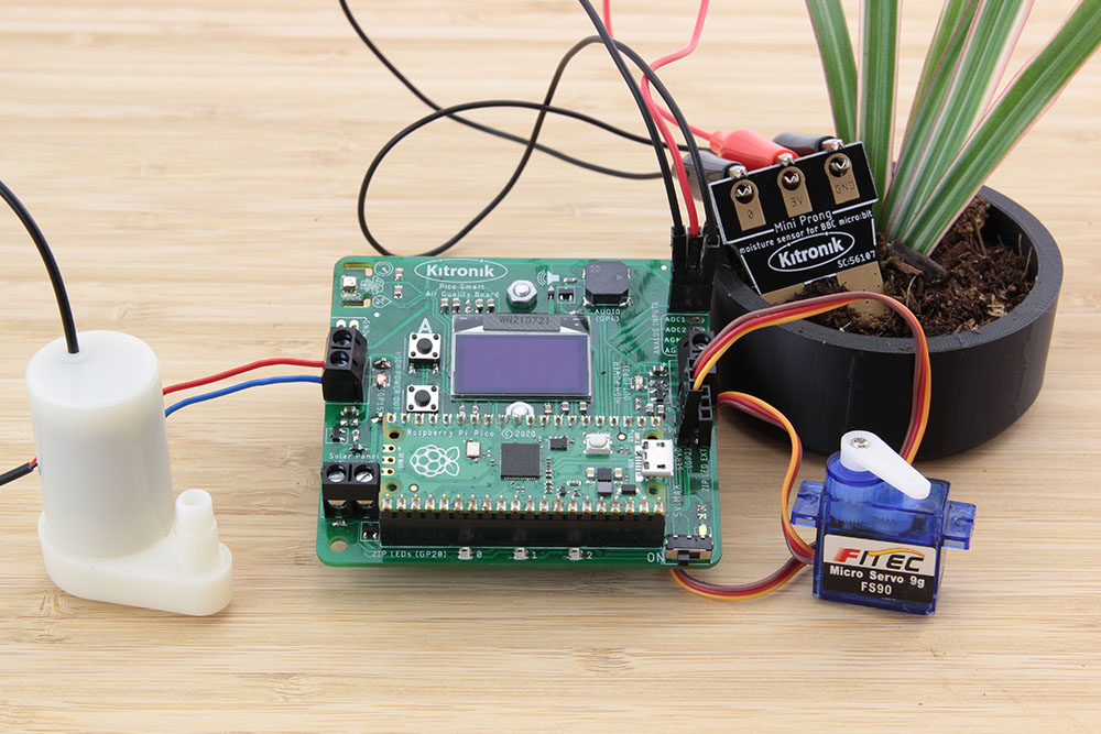
This tutorial works best if you have external devices which can be connected to the Pico Smart Air Quality Board inputs and outputs. The example programs here have used the following products available from Kitronik:
- Analogue Input: Mini Prong [56107] and 3 x Alligator Clip with Pigtail [2480]
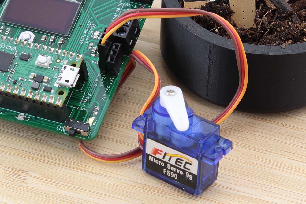
- Servo: Mini 180 Degree Resin Gear Servo SG90 [2565]
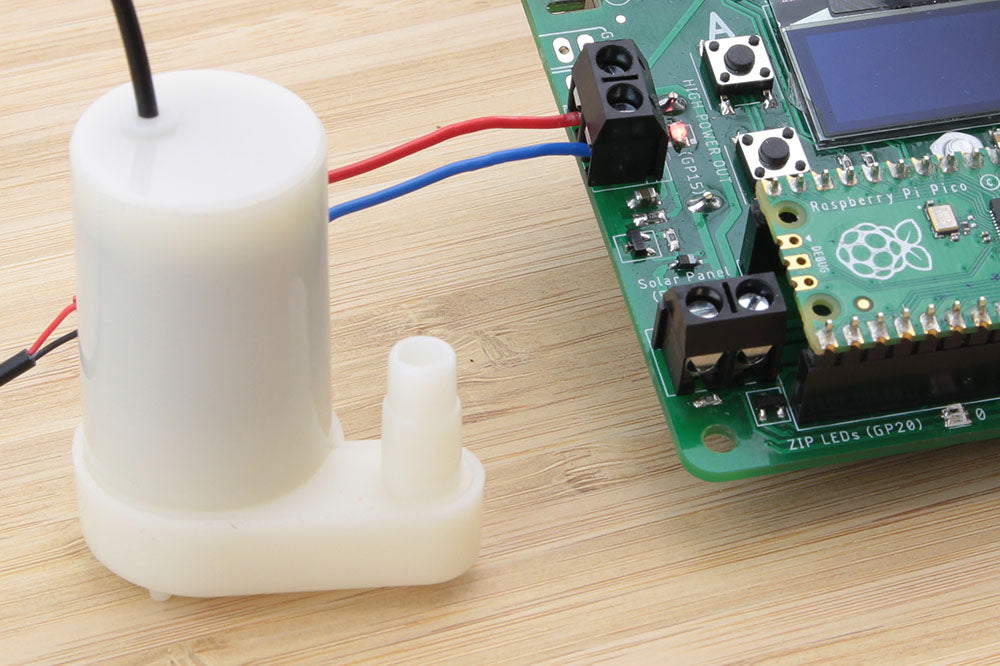
- Water Pump: 3V Vertical Submersible Water Pump [25110]
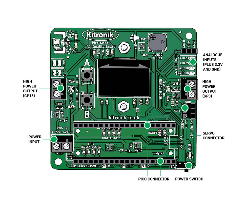
Analogue Inputs
As well as the onboard BME688 sensor, it is also possible to connect external devices to the board, including analogue sensors. There are three inputs (labelled ADC0, 1 and 2), three analogue grounds and a 3.3V, all located in the top right corner of the board, when the Pico is on the bottom edge. These inputs link directly to the Pico ADC (Analogue-to-Digital Converter), which, as the name suggests, will convert an analogue input voltage to a digital format which is then usable by the microprocessor. The range of the ADC output is 0 to 65535, providing a good resolution for measuring relatively small signal changes.
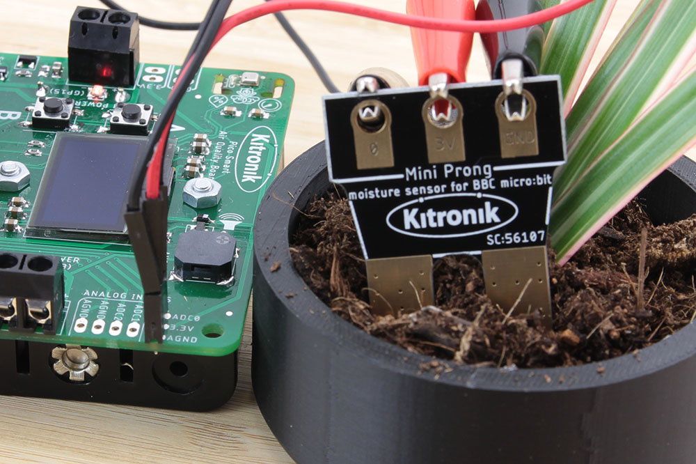
Two of the ADC connections are available as solder pads, but ADC0 has a pin socket connector which also includes an analogue ground and 3.3V, making it perfect for connecting something like the Mini Prong Moisture sensor, using crocodile clip to pin header leads.
With the Pico correctly mounted on the board and connected to Thonny,
Create and run the following code:
from PicoAirQuality import KitronikOLED, KitronikOutputControl
import time
oled = KitronikOLED()
output = KitronikOutputControl()
analogIn = machine.ADC(26) # ADC0 on the Pico Smart Air Quality Board
while True:
    # Analog Input
    oled.clear()

    oled.displayText("Analog In: " + str(analogIn.read_u16()), 1)

    oled.plot(analogIn.read_u16())

    oled.show()

    time.sleep_ms(100)
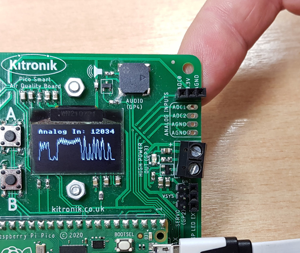
You should see the words ‘Analog In’ displaying on the top line of the OLED screen, followed by a value which updates continuously – this value is ADC reading from ADC0. The rest of the screen will be displaying a graph plot of the analogue input measurement. Try brushing your fingers across the solder pad connections underneath the ADC0 pin socket to vary the measured value.
If you have the Mini Prong connected, try using your fingers to connect across the electrodes. As you grip harder and make more contact across the probes, the ADC reading should increase, and vice versa.
Having multiple connections left ready on the board means there are lots of options for connecting other analogue sensors – just make sure their maximum output signal is no greater than 3.3V (this is the ADC limit on the Pico).
Servo Output
The board comes equipped with a set of male pin headers designed to work with a standard servo connector (just above the Pico USB connector), and some useful functions in the software module. Servos are a great way of adding some precise movement control to your project – maybe you have built a weatherproof enclosure for the board as a monitoring station, but want to open a panel each time you take a measurement to make sure it is accurate for the external environment.
Create and run the following code:
from PicoAirQuality import KitronikOLED, KitronikOutputControl
import time
oled = KitronikOLED()
output = KitronikOutputControl()


oled.clear()

# Servo

oled.displayText("Servo", 2)

oled.show()
while True:
    # Servo
    oled.clearLine(3)

    oled.displayText("Servo to 0", 3)

    oled.show()

    output.servoToPosition(0)

    time.sleep_ms(1000)

    oled.clearLine(3)

    oled.displayText("Servo to 180", 3)

    oled.show()

    output.servoToPosition(180)

    time.sleep_ms(1000)
You should see ‘Servo’ displaying on the OLED screen and the connected servo turning back and forth between 0 and 180° every second – the message on the screen will also give you the servo angle. If your servo doesn’t move check that the board is switched on, and that the servo ground wire (usually brown or black) is on the pin furthest from the Pico.
High-Power Outputs
There are two terminal blocks on the board which are designated as high-power outputs, one controlled by GP3 on the Pico and the other by GP15. These outputs are not directly linked to the Pico pins as the Pico can not supply a lot of current. Most microprocessor pins are designed for controlling signals, not powering devices. On the Pico Air Quality board the signal pins are used to control FETs (Field Effect Transistors). FETs act like a controlled gate, stopping or allowing current flow depending on the input signal; in this case, a current supply of up to 1A. These outputs are ideal for simple on/off control of something like a motor – this tutorial is using a small water pump.
Create and run the following code:
from PicoAirQuality import KitronikOLED, KitronikOutputControl
import time
oled = KitronikOLED()
output = KitronikOutputControl()


oled.clear()

# High-Power Outputs

oled.displayText("High-Power Out", 2)

oled.show()
while True:
    # High-Power Outputs
    oled.clearLine(3)

    oled.displayText("Outputs On", 3)

    oled.show()

    output.highPowerOn(15)

    output.highPowerOn(3)

    time.sleep_ms(1000)

    oled.clearLine(3)

    oled.displayText("Outputs Off", 3)

    oled.show()

    output.highPowerOff(15)

    output.highPowerOff(3)

    time.sleep_ms(1000)
You should see ‘High-Power Out’ displaying on the OLED screen and the connected water pump turning on and off every second – the message on the screen will also give the state of the outputs, ‘ON’ or ‘OFF’. You will also notice that there are some red indicator LEDs next to the terminal blocks – these are helpful for seeing when the outputs are on. The software functions are very straightforward, either turning on or off an output, calling the pin connected to the Pico.
Now that you have seen how the external connections work, why not try creating a larger project which incorporates extra sensors and controllable outputs?
Coding Resources:
The list of resources in the table below have been put together to introduce you to all of the features of the board. It is best to work through them in the order that they are laid out in the table.
| Online Tutorials – Pico Smart Air Quality Board. |
|---|
| Using the BME688 Sensor. |
| Using OLED and RTC. |
| The Buzzer, Buttons & ZIP LEDs. |
| Data Logging. |
| Analogue Input & Output Control. |